Do you have a question about the Topcon ES-101 and is the answer not in the manual?
Explains symbols used for warnings, cautions, prohibitions, and mandatory actions.
Covers safety warnings related to unit usage, disassembly, sun observation, and carrying case.
Details safety warnings for battery charging, usage, and handling of power cords and plugs.
Safety guidelines for tripod setup and Bluetooth wireless technology usage.
Specific safety advice for operating the instrument in low temperatures.
Guidelines for charging the battery, including temperature and storage recommendations.
Precautions to maintain waterproofing and dust resistance of the instrument.
Instructions on backing up data, battery care, clamp usage, and instrument maintenance.
General advice on handling, storage, and avoiding environmental factors affecting the instrument.
Classifies EDM device and laser pointer based on laser class and target type.
Critical warnings and cautions regarding safe laser beam usage, avoiding eye exposure and reflective surfaces.
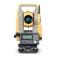
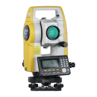
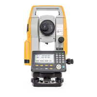
Identifies and labels the various physical components of the ES instrument.
Illustrates the different operational modes and their interconnections.
Details Bluetooth function availability and regulatory compliance.
Explains fundamental key operations like power, lighting, target switching, and laser pointer control.
Describes the information displayed on the instrument's screens in different modes.
Details accessing the Star Key menu for measurement settings and program selection.
Instructions for charging the battery, including temperature ranges.
Step-by-step instructions for installing and removing the battery.
Procedure for centering the instrument using the optical plummet eyepiece.
Procedure for leveling the instrument using circular and tilt levels.
Explains the concept of parallax and how to remove it for accurate readings.
Step-by-step instructions for turning the instrument ON, including password entry.
Step-by-step instructions for turning the instrument OFF, including battery status.
Details on setting the ES to "Slave" or "Master" mode for Bluetooth communication.
Explains how to establish a Bluetooth connection and notes battery consumption.
Details performing measurements using a data collector via Bluetooth.
Explains entering known point data and outputting JOB data via Bluetooth.
Procedure for basic cable settings to connect to external devices.
Procedure to measure the included angle between two points by setting horizontal angle to 0.
Procedure to reset the horizontal angle to a required value or hold it.
Explains angle measurement and outputting data to computers or peripherals.
Procedure to check the strength of the returned signal for accurate distance measurement.
Procedure for measuring distance and angle simultaneously.
How to recall previously measured distance and angle data.
Explains distance measurement and outputting data to external devices.
Explains coordinate measurement and outputting data to external devices.
Procedure for Remote Measurement (REM) to find heights of inaccessible points.
Methods for setting instrument station data via key input or coordinate registration.
Methods for setting the backsight angle using input or calculation.
Procedure to enter instrument station coordinates, heights, and azimuth angle.
Determines instrument station coordinates by measuring known points.
Finds 3D coordinates of a target using station data and measurements.
Sets out points using coordinates, calculating horizontal angle and distance.
Finds points based on horizontal angle and distance from the instrument.
Performs REM measurement to find points where targets cannot be installed directly.
Defines the baseline for line operations by inputting coordinates or observing two points.
Finds required point coordinates by inputting length and offset based on the baseline.
Measures horizontal and vertical distances from the measured point to the line.
Defines an arc by inputting parameters or observing points.
Finds coordinates of points along an arc using length and offset.
Defines the baseline for point projection.
Enters point coordinates and performs point projection.
Performs observation settings prior to topography observation.
Procedure for topography observation, measuring directions and recording data.
Finds offset points by entering horizontal distance from target point.
Offset measurement using angles, sighting directions to find offset points.
Measures distances between target and two offset points to find the target.
Finds distance and coordinate of a plane edge where direct measurement is not possible.
Finds distance and coordinates of a column center.
Measures distances between multiple points using observation or coordinates.
Changes the last measured point to the next starting position.
Calculates slope and horizontal area enclosed by known points via observation.
Calculates area using previously registered coordinates of points.
Finds intersection points between two reference points by specifying length or azimuth.
Calculates and adjusts coordinates of consecutively observed points in a traverse.
Records instrument station as a reference point before starting surveying.
Calculates center and width peg coordinates for straight lines.
Finds center and width peg coordinates for circular curves.
Finds center and width peg coordinates for spiral (clothoid) curves.
Finds center and width peg coordinates for parabolas.
Finds coordinates of cardinal points, centerline, and width pegs from 3 IP points.
Calculates angles from intersections for route surveying.
Performs calculations for a whole route containing multiple curves.
Enters Intersection Points (IPs) for route calculation.
Inputs curve properties like parameter A, radius, and offset for route calculation.
Checks and alters curve properties set in inputting curve elements.
Clears route data set for intersection points and curve elements.
Calculates cardinal points based on curve properties at specified intervals.
Finds coordinates of arbitrary points on calculated curves.
Calculates route widths and coordinates for center pegs using inverse width peg calculation.
Sets curve type and BP point for subsequent curve calculations.
Displays cross-section data recorded in a JOB, showing offset.
Sets the baseline by defining instrument height and observing points.
Measures target points and displays instrument station coordinates.
Stores instrument station coordinates, name, height, codes, operator, and environmental data.
Stores backsight station data and selects azimuth angle setting method.
Stores angle measurement values, target height, point name, and code.
Stores distance measurement data, target height, point name, and code.
Stores coordinate measurement data, target height, point name, and code.
Stores distance and coordinate data simultaneously with the same point name.
Prepares and records notes data in the current JOB.
Displays and searches data within the current JOB by point name.
Deletes recorded data from the currently selected JOB.
Selects the current JOB and Coordinate Search JOB from a list.
Clears data within a designated JOB.
Registers or deletes coordinate data of known points using key entry or external instrument.
Displays all coordinate data within the current JOB.
Saves and inputs codes in memory for use in data recording.
Displays the registered code list.
Connects ES to host computer and selects JOB data for output.
Connects ES to host computer to output code data.
Steps for correctly inserting the USB memory device into the ES.
Selects between T type and S type for communication format.
Saves measurement data, station data, etc., from a JOB to a USB device.
Saves code data to a USB memory device.
Loads known point data or code previously saved on USB to the current JOB.
Displays file information, edits file names, and deletes files.
Formats the USB memory device using quick format.
Explains the Config Mode and its sub-menus like Obs. condition, Instr. config.
Procedure to change the instrument's password.
Methods for restoring initial settings and initializing data.
Allows allocation of softkeys in OBS mode to suit measurement conditions and operator preferences.
Indicates poor measuring conditions or inability to sight the target.
Error message when a file name is not entered during USB data saving.
Occurs when known point coordinates coincide or calculation fails.
Indicates a sending/repetition error between ES and external equipment.
Error related to low battery voltage or depletion of the lithium battery.
Indicates a reception error in coordinate data from an external instrument.
Procedure to check and adjust the circular level bubble for proper instrument leveling.
Checks and cancels tilt zero point error for accurate angle measurements.
Measures and corrects collimation error for accurate angular observations.
Checks perpendicularity of the reticle to the horizontal axis.
Checks and adjusts the optical plummet for accurate centering.
Checks and adjusts the additive distance constant (K) for accurate distance measurements.
Checks and adjusts the laser plummet for accurate centering.
Ensures all necessary equipment is present before first use.
Lists optional accessories sold separately for the ES series.
Describes arrangements and compatibility of prism systems.
Lists available power supplies and their combinations for operating the ES.
Specifies telescope dimensions, magnification, and resolving power.
Details angle measurement types, units, accuracy, and display.
Specifies the type, minimum display, range, and automatic compensator settings.
Details measuring method, signal source, laser class, and measuring ranges.
Specifies minimum display values for fine, rapid, and tracking measurements.
Specifies maximum distance display for prism and reflectorless measurements.
Lists accuracy specifications for different measurement modes and target types.
Lists selectable measuring modes like fine, rapid, and tracking.
Specifies measuring times for fine, rapid, and tracking measurements.
Specifies input ranges for temperature and pressure for atmospheric correction.
Procedure to eliminate inaccuracy in the vertical circle 0 index for high precision measurements.
Explains how the instrument accounts for refraction and earth curvature in distance calculations.
Details FCC rules and compliance statements for the device.
Lists manufacturer information and product model details.
| Model | ES-101 |
|---|---|
| Type | Electronic Total Station |
| Waterproof/Dustproof | IP66 |
| Power Supply | Rechargeable Li-ion battery |
| Communication | USB |
| Operating Temperature | -20°C to +50°C |
| EDM Accuracy (Reflectorless) | ±(3mm + 2ppm x D) |