287
35. CHECKS AND ADJUSTMENTS
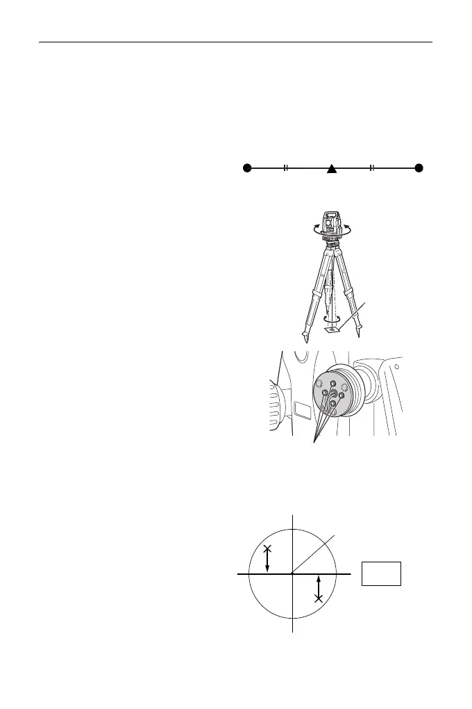
3. Note the current position (x) of the
laser beam.
4. Turn the upper part of the
instrument horizontally through
180° and note the new position (y)
of the laser beam.
Adjustment will bring the laser
beam to a point midway along a
line drawn between these two
positions.
5. Check the position of the desired
final position. Place a target so
that its center is aligned with the
desired final position.
The remaining deviation will be
adjusted using the 4 fine
adjustment screws.
:
• Be extremely careful to adjust all
the fine adjustment screws by
the same amount so that none
will be over-tightened.
• Turn screws clockwise to
tighten.
6. When the laser beam is on the
upper (lower) part of Fig. A the up/
down adjustment is made as
follows:
Insert the provided
hexagon key
wrench into
both the upper and lower
screws.
Desired final position
Target
Fine adjustment screws
Fig. A
Desired final position