165
25. ROUTE SURVEYING
25. ROUTE SURVEYING
This mode allows a variety of route surveying options widely used in civil
engineering measurement. Each menu allows the operator to initiate a string of
successive configuration/calculation/record/setting-out operations.
• The orientation of the instrument station and backsight station can be set as
necessary.
For backsight station settings, see"13.1 Entering Instrument Station
Data and Azimuth Angle".
• EDM settings can be set in the Route Surveying menu.
"33.2 EDM Settings"
• The point names and codes set when measurement results were recorded can
only be used in the Route Surveying menu.
• The Z-axis coordinate value in all Route Surveying work is always "Null" ("Null"
is not the same as "0").
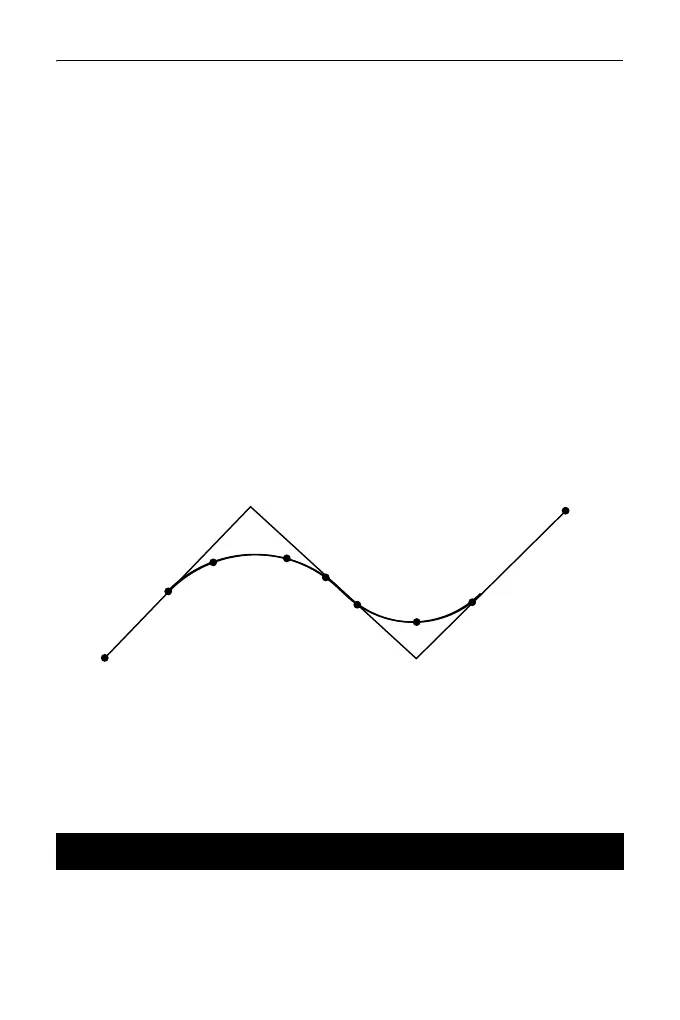
Symbols and terms used in Route Surveying
BP Point: route origin EP Point: route end-point
KA Point: clothoid curve origin KE Point: clothoid end-point
BC Point: circular curve origin EC Point: circular curve end-point
IP Point: point of intersection SP Point: circular curve midpoint
Offset: reference point Follow-up distance: target point
follow-up distance follow-up distance
The instrument station to be used as the reference point is recorded, as
necessary, prior to starting surveying.
25.1 Instrument Station Settings
BC
KA1
KE1
KA2
KE2
EC
EP
BP
Curve 1
Curve 2
IP
SP