40
10. CHECK AND ADJUSTMENTS
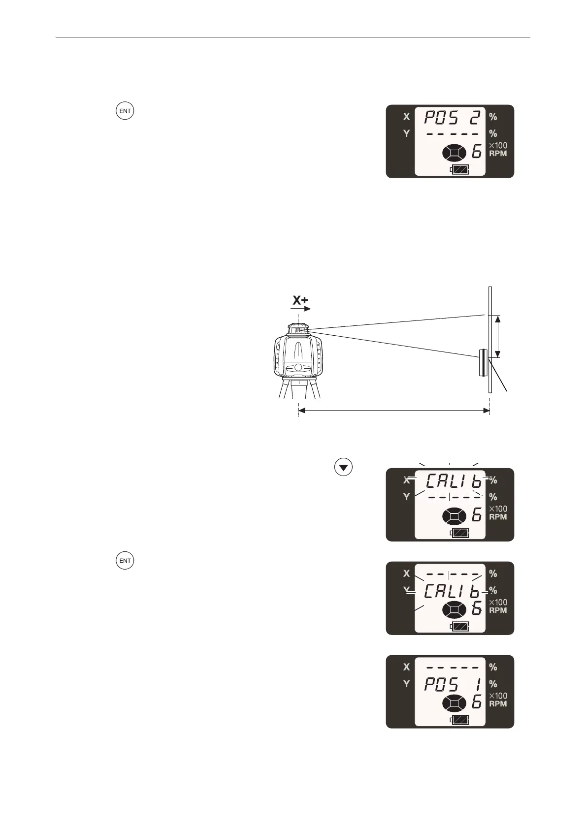
5. Detect the center of the laser beam on the wall with the LS-80X and
mark it. (X1)
6. Press the key.
7. Loosen the centering screw and rotate the RL-HV 180°, and tighten
the screw to secure. The RL-HV X+ surface will face the wall. When
rotating the RL-HV, ensure that the instrument height is not
misaligned.
The RL-HV self-leveling is complete and the laser will emit.
8. Detect the center of the LS-80X laser
beam on the wall and mark (X2).
If the difference in height of the two laser
beam marks (X1 and X2) is less than 5
mm, no adjustment is required. Turn off
the power. If the difference is more than 5
mm, follow adjusting steps for horizontal
rotation.
" PROCEDURE Adjusting"
9. Perform check on the Y axis after the
adjustment for the X axis is complete.
When checking and adjusting the Y axis direction, press the
key.
Press the key.
The screen will switch to the Y axis check and adjusting mode.
• A difference between X1 and X2 is more than 40 mm (±90"), it is outside of the adjustment range. Contact
your local dealer.
X2 laser beam
50m
X2 laser position
X2
X1
 Loading...