Do you have a question about the Topwisdom TL-403 and is the answer not in the manual?
Step-by-step instructions for installing the CorelDRAW direct output feature.
Procedure for removing the CorelDRAW direct output software.
Instructions for installing the CAD direct output software.
Procedure for removing the CAD direct output software.
Guide to installing the necessary USB drivers for device connection.
Instructions for configuring USB port assignments for communication.
Steps to check the current COM port assigned to the device by the computer.
Guide to modifying the COM port number if issues arise.
Configuration steps for setting the IP address for network communication.
Visual representation of the system's electrical connections and components.
Technical drawings showing physical dimensions for panel and mainboard mounting.
Dimensions for installing the operation panel.
Dimensions for mounting the main control board.
Specific instructions for various wiring connections.
Overview of the main interface connectors and their pinouts.
Detailed diagrams illustrating wiring for motors and other components.
Explanation of different interface ports and their functions.
Details on the system's 5V power supply interfaces and connections.
Information on using the USB disk port for file transfer.
Details on connecting the system to a PC via USB.
Information regarding network connectivity for PC communication.
Explanation of the driver interface and output signals.
Connection details for controlling the laser power supply.
Description of input signals and limit interface connections.
Visual diagram illustrating input signal connections and logic.
General introduction to the system's features and benefits.
Important safety precautions and warnings for operating the equipment.
Recommended environmental conditions for optimal system operation.
Requirements for proper power connection and electrical grounding.
Specific voltage and current requirements for the system's power supply.
Guidelines for ensuring safe and effective electrical grounding.
List of accessories included with the laser engraving control system.
Troubleshooting steps for system reset errors and unresponsive buttons.
Answers to common issues related to laser power and light output.
Troubleshooting for problems with PC connectivity and port communication.
Solutions for errors encountered when reading or writing to a U disk.
Instructions for using the software with CorelDRAW for direct output.
How to configure parameters for different layers in the engraving process.
Steps for setting the machine's coordinate system and origin points.
How to define the cutting order and start points for shapes.
Guide for controlling individual axis movements of the machine.
Process for sending engraving jobs to the machine.
How to manage and configure machine parameters within the software.
Explanation of the function of buttons in the software toolbar.
Detailed guide for setting equipment parameters and factory defaults.
Instructions for importing embroidery file formats into the software.
Guide on importing bitmap images for engraving.
How to adjust curve accuracy for smoother operation.
Instructions for using the software with CAD designs for direct output.
How to handle text and annotations from AutoCAD designs for engraving.
Explanation of gradient carving effects and their visual representation.
Understanding and setting the machine's coordinate system.
Additional notes on the carving process and output effects.
Further details and solutions for software and CAD output issues.
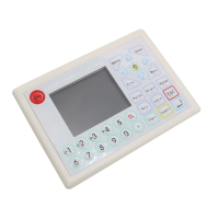
Overview of the panel layout and the function of each button.
Description of the main control panel interface.
Detailed explanation of the purpose of each button on the panel.
Explanation of the main operating interface displayed on the machine.
Description of the power status interface.
Overview of the system's standby screen and its elements.
Interface for adjusting the machine's movement and work speeds.
Interface for setting and controlling laser power levels.
Interface for previewing the range or path of the laser head.
Interface for manual control of individual machine axes.
Interface for selecting files from memory or U disk for processing.
Interface for managing files stored on a U disk.
Access to the main menu for system configuration options.
Options for configuring how files are saved and processed.
Settings that integrate various machine and software functions.
Configuration options specifically for the laser device.
Settings related to the physical configuration and type of equipment.
Configuration parameters for each axis of the machine's movement.
Settings for returning axes to their origin positions.
User-defined settings and preferences for machine operation.
Displays system status, uptime, and statistical data.
Options for setting and managing machine access passwords.
Tools for testing system components and functionality.
| Brand | Topwisdom |
|---|---|
| Model | TL-403 |
| Category | Control Systems |
| Language | English |