Shenzhen Topwisdom Technology Co., Ltd
The connection ways of switch input signal:
When using approaching switch, the corresponding parameters of upper PC must
be set as ―Negative‖ by NPN; the corresponding parameters of upper PC must be
set as ―Positive‖ by PNP.
When using straight or magnetic induction switch, the corresponding parameters
of upper PC must be set as ―Negative‖ while receiving signal + XGND;the
corresponding parameters of upper PC must be set as ―Positive‖ while receiving
signal + EX5V.
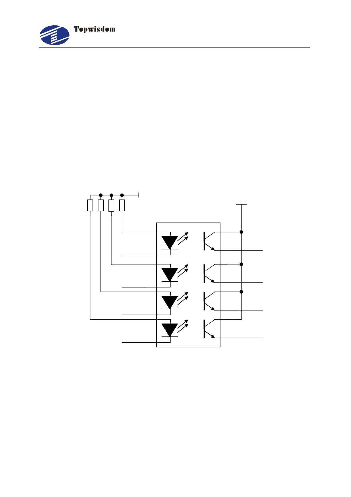
2.4.8 Input Signal Diagram
Fig 2-14