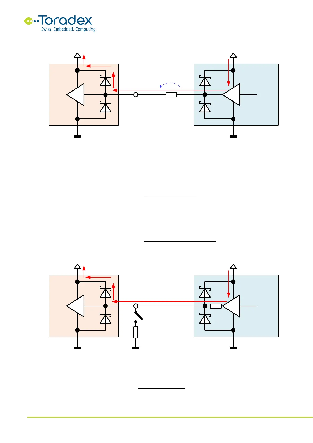
Figure 37: Measuring backfeeding current
If a signal features a series resistor, the voltage drop can be used to measure the backfeeding
current. Some signals might not have a series resistor for measuring the current. By adding a load
resistor to the backfeeding signal (for example, a 180Ω resistor), the voltage with and without extra
load can be measured. This allows to estimate the internal resistance of the driver by using the
following formula:
With the help of the estimated internal driver resistance, the backfeeding current on the pin can be
estimated by using the following formula (V
peripheral IO rail
is the peripheral rail voltage, V
backfeeding
is the
voltage on the signal without the extra load resistor):
Figure 38: Evaluating the internal resistance of the driver
With the help of these formulas, the measured values in Figure 38 would lead to the following
internal resistance and backfeeding current: