the hydraulic uid to drain from the hose and
tank into the pan.
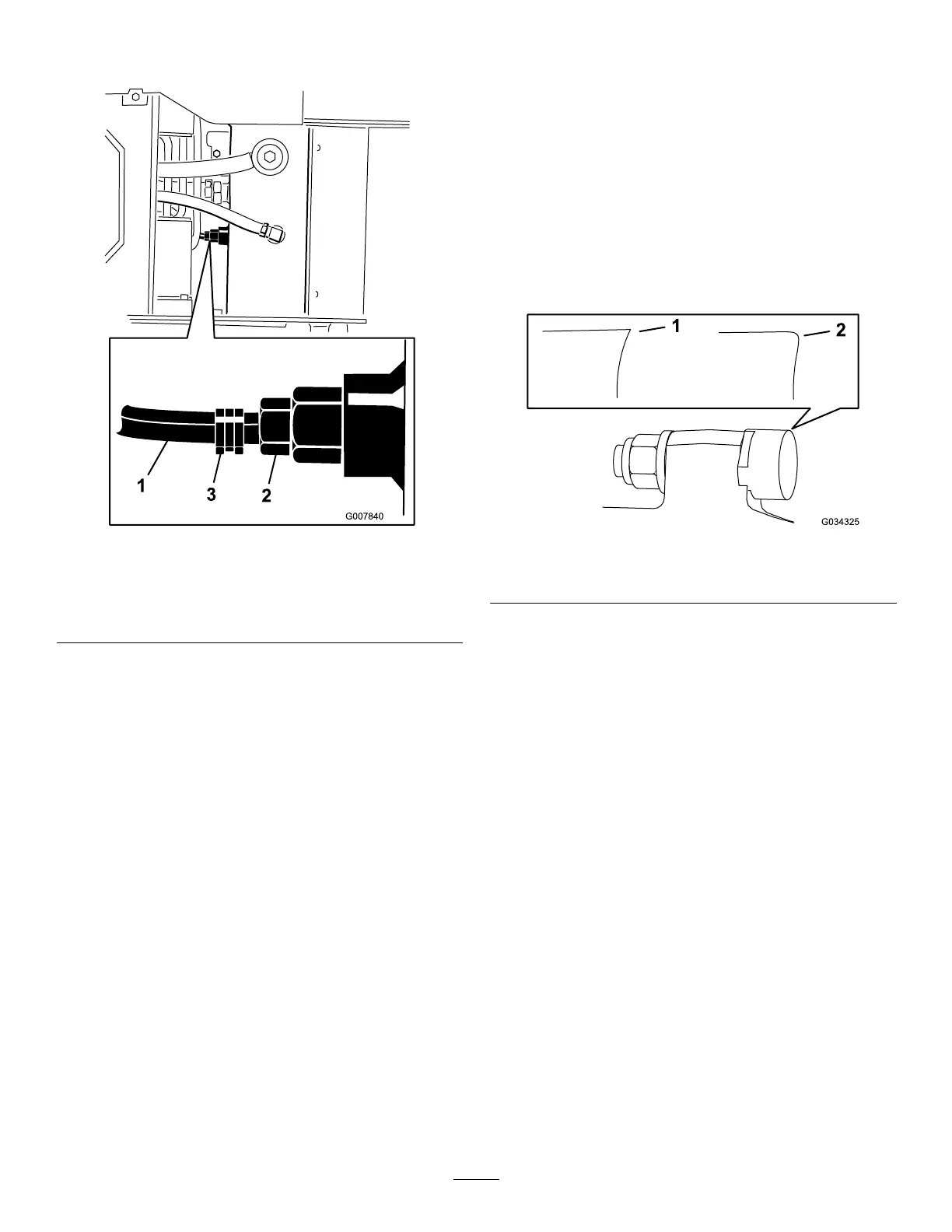
g007840
Figure 56
1. Hose
2. Hydraulic-tank tting
3. Hose clamp
8. When nished, install the hose onto the tting
and secure it with the hose clamp.
Note: Dispose of the used oil at a certied
recycling center .
9. Fill the hydraulic tank with hydraulic uid; refer
to Hydraulic Fluid Specications ( page 37 ) .
10. Install the hydraulic lter and ller cap ( Figure
54 ) and torque the bolt on top to 13 to 15.5 N∙m
(1 10 to 140 in-lb).
1 1. Start the engine and let it run for a few minutes.
12. Shut of f the engine.
13. Check the hydraulic-uid level and top it of f if
necessary; refer to Checking the Hydraulic-Fluid
Level ( page 37 ) .
14. Clean up any spilled uid.
15. Install the top cover .
Grinder Maintenance
Replacing the T eeth
Service Interval : Before each use or daily —Check
the condition of the teeth; rotate
or replace any that are worn or
damaged and torque the nuts for all
teeth.
Due to the high amount of wear placed on the teeth,
you need to rotate and replace them periodically
( Figure 57 ).
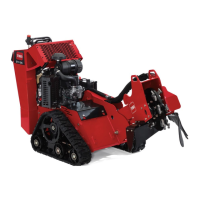
g034325
Figure 57
1. Sharp tooth
2. W orn tooth
Each tooth is indexed with 3 positions so you can
rotate it twice, exposing a new sharp edge before
replacing the tooth. T o rotate a tooth, loosen the nut
securing the tooth ( Figure 58 ). Push the tooth forward
and rotate it one third of a turn, bringing an unused
edge to the outside. T orque the nut securing the tooth
to 68 N∙m (50 ft-lb).
T o replace a tooth, remove the nut securing the tooth
to remove it, then install a new tooth, spacer , and
nut in the same position ( Figure 58 ). T orque the nut
securing the tooth to 68 N∙m (50 ft-lb).
39