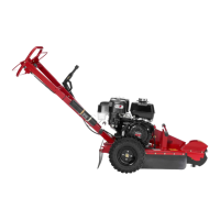
Setup
Loose Parts
Use the chart below to verify that all parts have been shipped.
Procedure Description
Qty .
Use
Grinder control lever
1
1
Jam nut 1
Install the grinder control lever .
2
No parts required
–
Check the uid levels.
3
No parts required
–
Charge the battery .
1
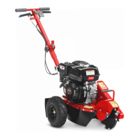
Installing the Grinder
Control Lever
Parts needed for this procedure:
1
Grinder control lever
1 Jam nut
Procedure
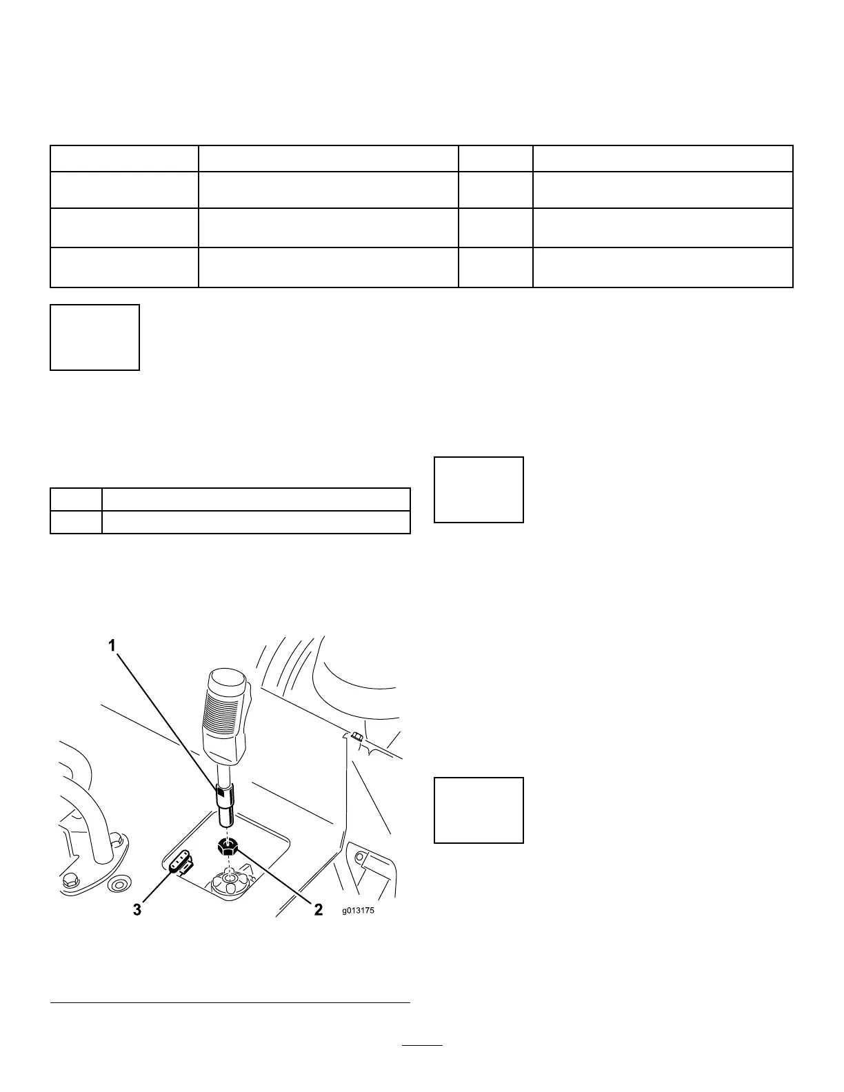
1. Thread the jam nut onto the grinder control lever
( Figure 3 ).
g013175
Figure 3
1. Grinder control lever
3. 4-pin connector
2. Jam nut
2. Thread the grinder control lever into the
receptacle on the control panel ( Figure 3 ).
3. With the trigger oriented forward, tighten the jam
nut against the receptacle to secure the lever in
place ( Figure 3 ).
4. Connect the wire on the lever to the 4-pin
connector under the control panel ( Figure 3 ).
2
Checking the Fluid Levels
No Parts Required
Procedure
Before starting the engine for the rst time, check
the engine-oil and hydraulic-uid levels. Refer to the
following sections for more information:
• Checking the Engine-Oil Level ( page 24 )
• Checking the Hydraulic-Fluid Level ( page 37 )
3
Charging the Battery
No Parts Required
Procedure
Charge the battery; refer to Charging the Battery
( page 29 ) for more information.
8