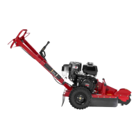
Product Overview
g018769
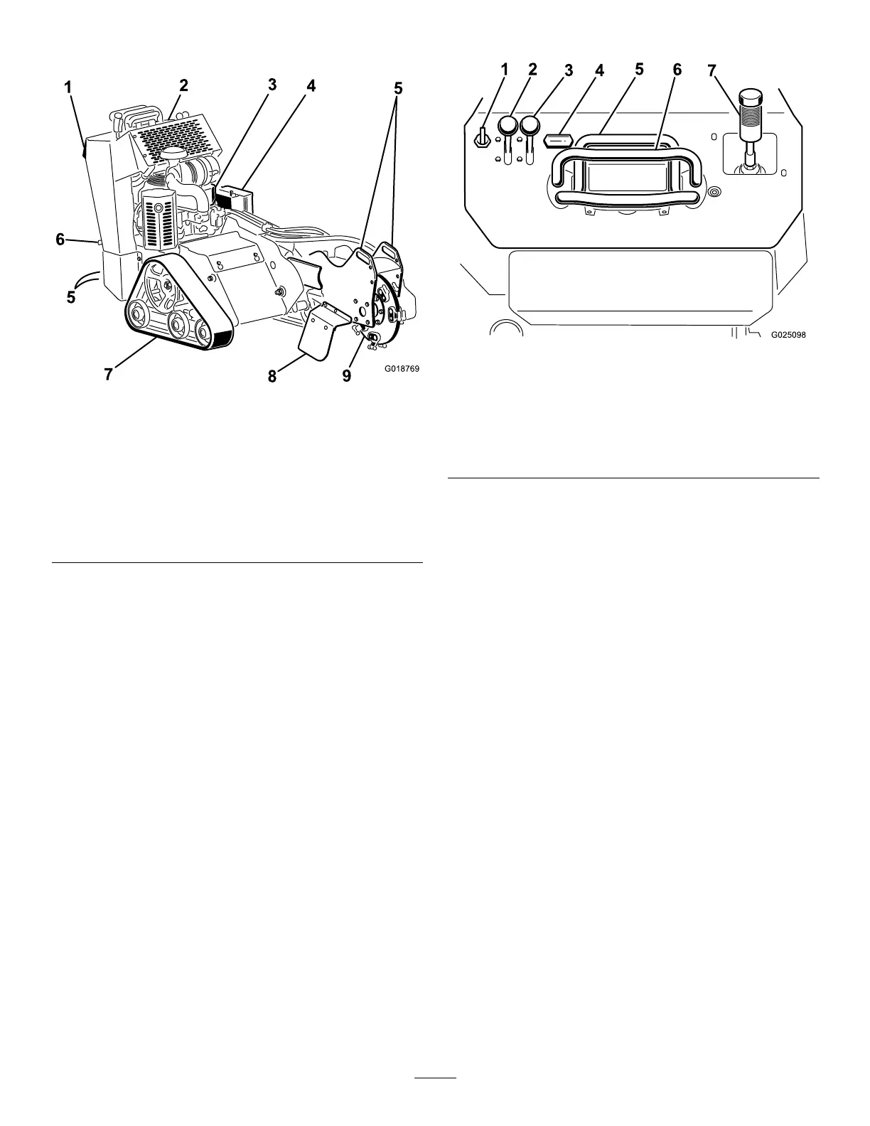
Figure 4
1. Reverse safety
plate
4. Battery 7. T rack
2. Control panel 5. T ie-down/lift
point
8. Chip shield
3. Engine 6. Parking-brake
lever
(machines with
CE kit only)
9. Grinder
Controls
Become familiar with all the controls ( Figure 5 ) before
you start the engine and operate the machine.
Control Panel
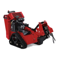
g025098
Figure 5
1. Key switch 5. T raction control
2. Throttle lever
6. Reference bar
3. Choke lever 7. Grinder
control/hydraulic-lift lever
4. Hour meter
Key Switch
The key switch, used to start and shut of f the engine,
has 3 positions: O FF , R UN , and S TART . Refer to
Starting the Engine ( page 15 ) .
Throttle Lever
Move the control forward to increase the engine speed
and rearward to decrease the engine speed.
Choke Lever
Before starting a cold engine, move the choke lever
forward. After the engine starts, regulate the choke
to keep the engine running smoothly . As soon as
possible, move the choke lever all the way rearward.
Note: A warm engine requires little or no choking.
Hour Meter
The hour meter displays the number of hours of
operation that have been logged on the machine.
9