oftheuid.TheColdlevelshowsthelevelof
theuidwhenitisat24°C(75°F).TheHot
levelshowsthelevelofuidwhenitisat107°C
(225°F).
Forexample:Iftheuidisatambient-air
temperature,about24°C(75°F),llonlytothe
Coldlevel.Iftheuidisabout65°C(150°F),ll
tohalfwaybetweentheHotandColdlevels.
8.Replacethehydraulicreservoircapandtighten
ituntilitissnug(Figure60).
Note:Donotovertightenthereservoircap.
9.Installtheconsolepad;refertoRemovingthe
ConsolePad(page32).
ChangingtheAuxiliaryHydraulic
ReservoirFluidandFilter
ServiceInterval:Aftertherst100hours
Every250hoursthereafter
1.Shutofftheengine,engagetheparkingbrake,
removethekey,andwaitforallmovingpartsto
stopbeforeleavingtheoperatingposition.
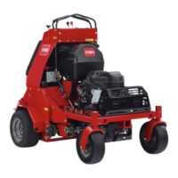
2.Carefullycleanareaaroundthefrontofthe
auxiliarypump,llcapforthereservoir,andlter
(Figure61).
Important:Ensurethatnodirtor
contaminationentershydraulicsystem.
g026008
Figure61
3.Atthefrontoftheauxiliaryhydraulicpump,
removetheinlethosefromthehydraulictting
inthepump,placetheendofthehoseinadrain
container,andallowtheuidtodrain(Figure62).
g026010
Figure62
1.Hydraulictting(auxiliary
hydraulicpump)
3.Draincontainer
2.Inlethose
4.Cleanaroundthettingforthehydraulicpump.
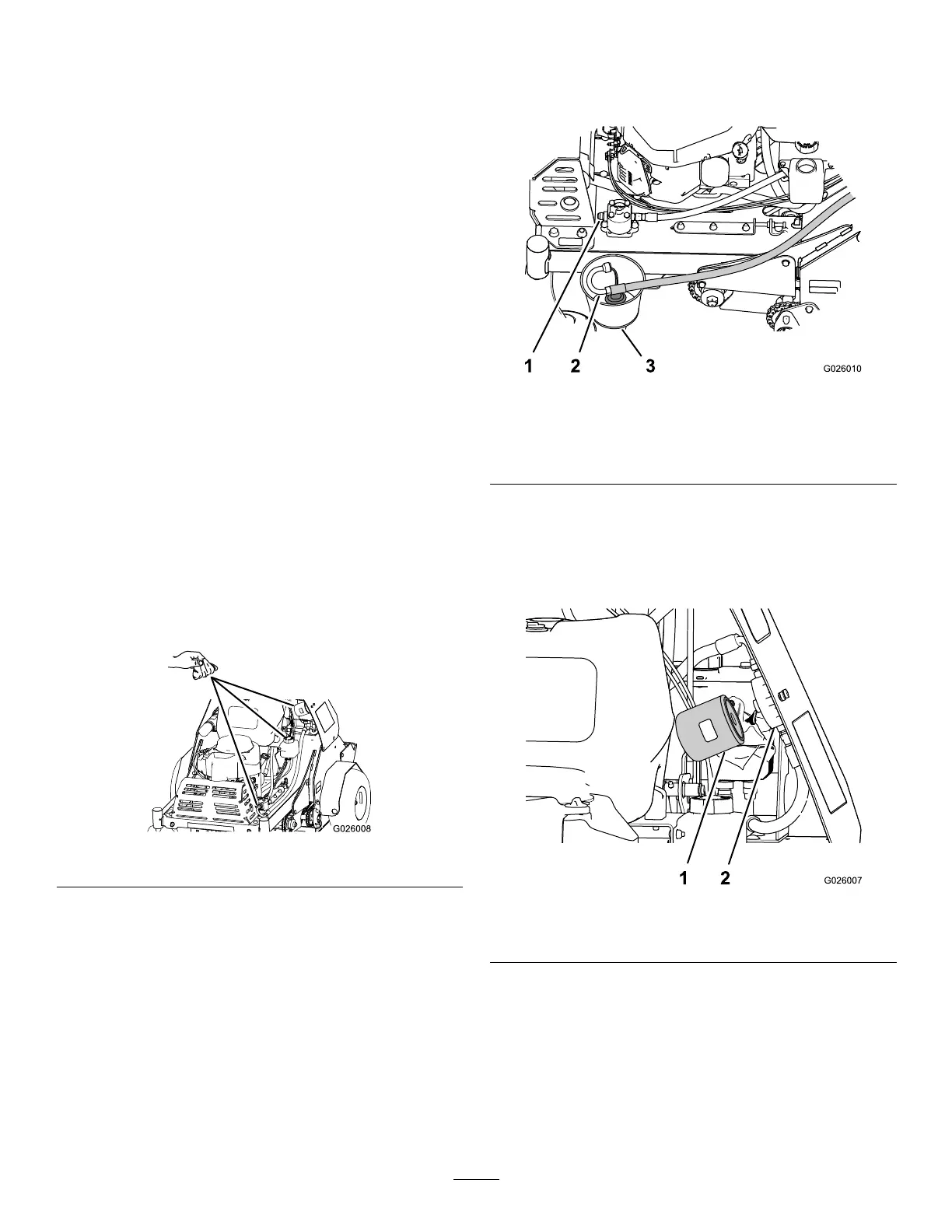
5.Rotatetheauxiliaryhydrauliclter
counterclockwiseandremoveitfromthe
baseofthelteradapter(Figure63).Allowthe
uidtodrain.
g026007
Figure63
1.Auxiliaryhydrauliclter
2.Filteradapter
6.Applyathincoatofspecieduidontotheseal
ofthenewhydrauliclter.
7.Installthelterbyrotatingitclockwiseontothe
lteradapteruntilthesealcontactsthelter
adapter,thentightenthelteranadditional2/3
to3/4turn(Figure63).
8.Installtheinlethoseontothettinginthepump
andtorquethehosettingto50N∙m(37ft-lb).
52