g027392
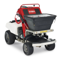
Figure42
1.Strainer(sprayertank)2.Pump-shutoffvalve
7.Starttheengineandsetthethrottlemidway
betweentheSLOWandFASTpositions.
8.Setthesprayer-pumpswitchtotheONposition
(Figure43).
g033348
Figure43
1.Sprayer-pressurecontrol5.Spraywand
2.Agitation-pumplever
6.Sprayer-pressuregauge
3.Narrow-spraypatternlever
7.Sprayer-pump/tank-agitation
switch
4.Wide-spraypatternlever
8.Sprayer-wand-pressure
control
9.MovethethrottletotheFASTposition.
10.Pullrearwardonthetank-agitationlevertothe
ONposition.
Note:Thewaterinthetankwillcirculate.
11.Addthespeciedamountofchemical
concentratetothetankasdirectedbythe
chemicalmanufacturer.
Important:Ifyouareusinga
wettable-powderchemical,mixthe
powderwithasmallamountofwatertoform
aliquidslurrybeforeaddingthechemical
mixturetothetank.
12.Addremainingwatertothetankandinstallcap
ontothellerneckofthetank.
Note:Allowthecontentofthesprayertankto
mixthoroughly.
EmptyingtheSprayerTank
Operatorsuppliedequipment:
•Adrainhosewitha1/2–14inchNPTmalecoupling
•Adraincontainer(capacityvarieswithremaining
sprayertankcontent)
•PTFEthreadsealant
1.Movethemachinetoalevelsurfaceatthe
designatedareaforemptyingandcleaningthe
sprayertank,movemotion-controllevertothe
NEUTRALposition,shutofftheengine,waitforall
movingpartstostop,removekey,andengage
parkingbrake.
2.Removetheplugfromthedrainvalveforthe
sprayertank(Figure44).
Note:Thedrainvalveislocatedattheleftside
ofthemachine.
g025542
Figure44
1.Drainvalve2.Plug
3.Threadadrainhose(operatorprovided)intothe
endofthedrainvalve.
4.Putthefreeendofthedrainhoseintoa
containerwithenoughcapacitytoholdthe
remainingcontentofthesprayertank.
40