g009039
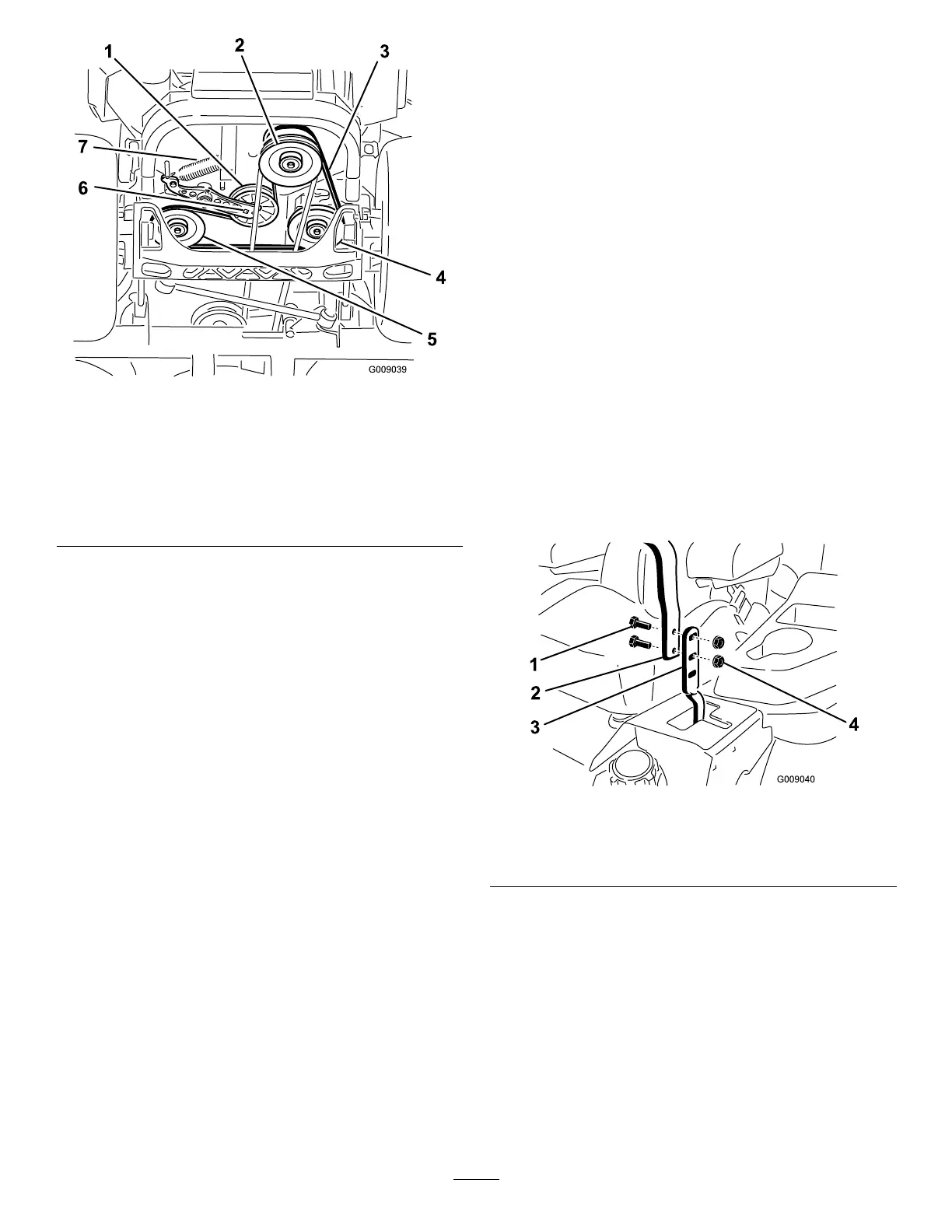
Figure 95
1. Idler pulley
5. Left hydraulic-pump pulley
2. Clutch pulley 6. Square hole in the idler
arm
3. Pump-drive belt 7. Idler spring
4. Right hydraulic-pump
pulley
5. Use a ratchet in the square hole in the idler arm
to remove the idler spring ( Figure 95 ).
6. Unhook the idler spring from the frame ( Figure
95 ).
7. Remove the belt from the hydraulic-unit-drive
pulleys and the engine pulley .
8. Install the new belt around engine pulley and
the 2 drive pulleys.
9. Using a ratchet in the square hole in the idler
arm, install the idler spring to the frame ( Figure
95 ).
10. Install the mower belt; refer to Replacing the
Mower Belt for Side-Discharge Mower Decks
( page 62 ) or Replacing the Mower Belt for
Rear-Discharge Mower Decks ( page 63 ) .
Controls System
Maintenance
Adjusting the
Control-Handle Position
There are 2 height positions for the control
levers—high and low . Remove the bolts to adjust the
height for the operator .
1. Park the machine on a level surface, disengage
the blade-control switch (PT O), and engage the
parking brake.
2. Shut of f the engine, remove the key , and wait
for all moving parts to stop before leaving the
operating position.
3. Loosen the bolts and ange nuts installed in the
levers ( Figure 96 ).
4. Align the levers in the front-to-rear position by
bringing the levers together to the N EUTRAL
position, and slide them until they are aligned,
then tighten the bolts ( Figure 97 ).
g009040
Figure 96
1. Bolt (2) 3. Control lever
2. Handle
4. Nut (2)
65