This regains some up and down adjustment on
each of the 4 deck links.
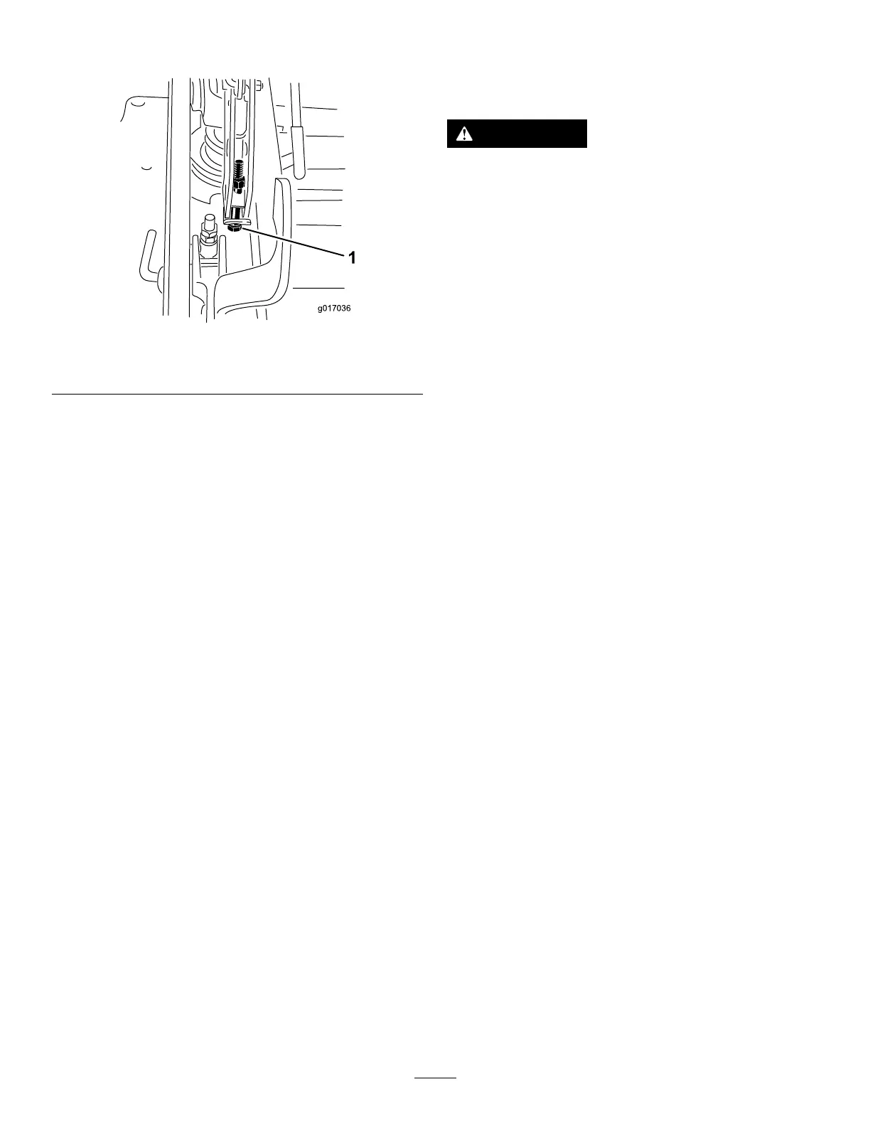
g017036
Figure 120
1. Single-point adjustment bolt
13. T ighten the 2 bolts at the bottom of the
height-of-cut plate ( Figure 1 18 ).
Note: In most conditions, the back blade tip
should be adjusted 6.4 mm (1/4 inch) higher
than the front.
14. T orque the 2 bolts to 37 to 45 N∙m (27 to 33 ft-lb).
15. On both sides of the deck, measure from the
level surface to the back tip of the blade (postion
B) as shown in Figure 1 15 .
Note: The measurement should read 8.3 cm
(3-1/4 inches)
16. Fine tune the screw adjuster by turning it to get
8.3 mm (3-1/4 inches) height ( Figure 1 17 ).
T o increase the height, turn the adjustment nut
clockwise; to decrease, turn counterclockwise.
17. Measure until all 4 sides are the correct height.
18. T ighten all of the nuts on the deck-lift-arm
assemblies.
19. For side-discharge machines, lower the
discharge chute.
Removing the Mower Deck
Lock out the spring-loaded deck arms before servicing
or removing the mower deck.
W ARNING
Deck-lift arm assemblies have stored energy .
Removing the deck with out releasing the
stored energy can cause serious injury or
death.
Do not attempt to disassemble the deck from
the front frame without locking out the stored
energy .
1. Park the machine on a level surface, disengage
the blade-control switch (PT O), and engage the
parking brake.
2. Shut of f the engine, remove the key , and wait
for all moving parts to stop before leaving the
operating position.
3. Place the height adjustment pin in the 7.6 cm (3
inch) cutting-height location.
Note: This locks the deck-lift arms in the lowest
position when the deck is removed and the
stored energy in the deck spring is released.
4. Remove the belt covers.
5. Lift up the oor pan and insert a ratchet into
the square hole in the deck idler ( Figure 121 or
Figure 122 ).
6. Rotate the deck idler clockwise, lift up on the
belt-guide tab (rear-discharge machines only),
and remove the mower belt ( Figure 121 or
Figure 122 ).
75