3. Apply copper-based lubricant or grease to the
threads of the blade bolt as needed to prevent
seizing. Install the blade bolt nger-tight.
4. Place a wrench on the at of the spindle shaft
and torque the blade bolt to 75 to 81 N∙m (55
to 60 ft-lb).
Leveling the Mower Deck
1. Park the machine on a level surface, disengage
the blade-control switch (PT O), and engage the
parking brake.
2. Shut of f the engine, remove the key , and wait
for all moving parts to stop before leaving the
operating position.
3. Check the tire pressure in the drive tires; refer to
Checking the T ire Pressure ( page 56 ) .
4. Position the transport lock in the latching
position.
5. Push the deck-lift pedal all the way forward
and the deck latches at the 14 cm (5-1/2 inch)
transport position ( Figure 1 14 ).
g027343
Figure 1 14
1. Deck-lift pedal
3. T ransport lock
2. Height-of-cut pin
6. Insert the height-adjustment pin into the 7.6 cm
(3 inches) cutting-height location.
7. Release the transport lock and allow the deck to
lower to the cutting height.
8. For side-discharge machines, raise the
discharge chute.
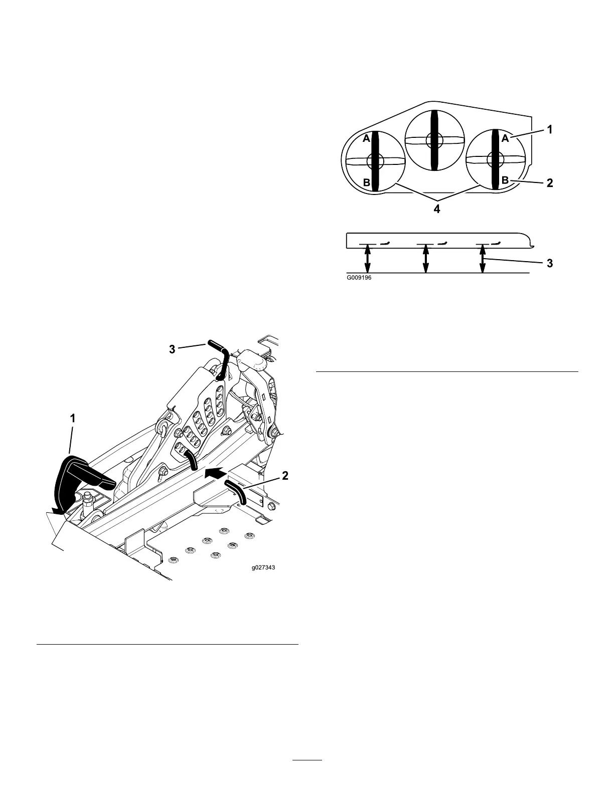
9. On both sides of the deck, measure from the
level surface to the front tip of the blade (Postion
A) as shown in Figure 1 15 .
Note: The measurement should read 7.6 mm
(3 inches)
g009196
Figure 1 15
1. 7.6 cm (3 inch) at position
A is correct
3. Measure here from the
blade tip to the hard
surface
2. 8.3 cm (3-1/4 inch) at
position B is correct
4. Measure at position A and
B on both sides
10. Fine-tune the adjustment nut on the front
deck-lift assembly by turning it ( Figure 1 16 or
Figure 1 17 ).
Note: T o increase the height, turn the
adjustment nut clockwise; to decrease the
height, turn the nut counterclockwise.
Note: If the front deck links do not have enough
adjustment to achieve accurate cut height, you
can use the single-point adjustment to gain
more adjustment.
73