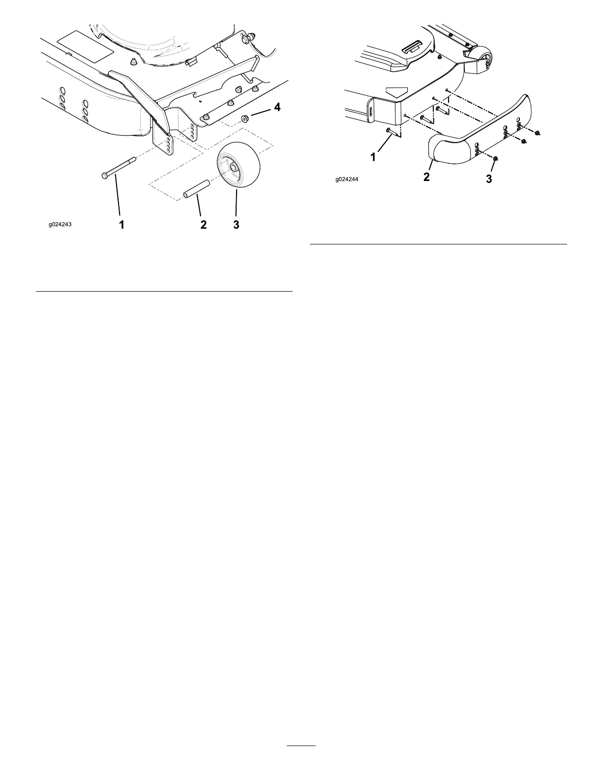
g024243
Figure 33
1. Bolt 3. Anti-scalp roller
2. Bushing 4. Flange nut
Adjusting the Skid(s)
For Machines with Rear Discharge
Mount the skids in the lower position when operating
in height of cuts higher than 64 mm (2-1/2 inches) and
in the higher position when operating in height of cuts
lower than 64 mm (2-1/2 inches).
Note: When the skids become worn, switch the skid
to the opposite sides of the mower , ipping them
over . This allows you to use the skids longer before
replacing them.
1. Park the machine on a level surface, disengage
the blade-control switch, and engage the parking
brake.
2. Shut of f the engine, remove the key , and wait
for all moving parts to stop before leaving the
operating position.
3. Remove the carriage bolts and nuts from each
skid ( Figure 34 ).
g024244
Figure 34
1. Carriage bolt
3. Nut
2. Skid
4. Move each skid to the desired position and
secure them with the carriage bolts and nuts.
Note: Only use the top or center sets of holes
to adjust the skids. The bottom holes are used
when switching sides on the mower deck, at
which time they become the top holes on the
other side of the mower .
5. T o prevent damaging the skid, torque the
carriage bolts and nuts for each skid to 12.4 to
14.7 N∙m (1 10 to 130 in-lb).
Adjusting the Flow Bafe
Knob
For Machines with Side Discharge
This procedure applies only to machines with the
ow baf e knob. Certain models have nuts and bolts
instead of the ow baf e knob that you can adjust the
same way .
Y ou can adjust the mower discharge ow for dif ferent
types of mowing conditions. Position the knob and
baf e to give the best quality of cut.
1. Park the machine on a level surface, disengage
the blade-control switch, and engage the parking
brake.
2. Shut of f the engine, remove the key , and wait
for all moving parts to stop before leaving the
operating position.
3. Loosen the knob.
4. Slide the knob to the desired position.
5. T ighten the knob.
33