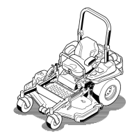
Figure87
1.Deck-liftpedal
3.Transportlock
2.Height-of-cutpin
6.Inserttheheight-adjustmentpinintothe7.6cm(3
inch)cutting-heightposition.
7.Releasethetransportlockandallowthedecktolower
tothecuttingheight.
8.Raisethedischargechute.
9.Onbothsidesofthedeck,measurefromthelevel
surfacetothefronttipoftheblade(PositionA);refer
toFigure88.
Note:Themeasurementshouldread7.6mm(3
inches).
Figure88
1.7.6cm(3inches)at
positionAiscorrect
3.Measurehere,fromthe
bladetip,tothehard
surface
2.8.3cm(3–1/4inches)at
positionBiscorrect
4.MeasureatpositionAand
Bonbothsides
10.Ifneeded,loosentheangedlocknutonthesideofthe
yokeandthejamnutontop.Fine-tunetheadjuster
screwbyturningittoget7.6mm(3inch)height
(Figure89).
Note:Toincreasetheheight,turntheadjuster
screwclockwise;todecreasetheheight,turnit
counterclockwise.
Figure89
1.Flangedlocknut3.Jamnut
2.Adjusterscrew4.Yoke
11.Ifthefrontdecklinksdonothaveenoughadjustment
toachievetheaccuratecutheight,youcanusethe
singlepointadjustmentcanbeutilizedtogainmore
adjustment.
12.Toadjustthesinglepointsystem,loosenthe2boltsat
thebottomoftheheight-of-cutplate.RefertoFigure
90.
56