WARNING
Abladethatisbentordamagedcould
breakapartandcouldseriouslyinjureor
killyouorbystanders.
•Alwaysreplacebentordamaged
bladewithanewblade.
•Neverleorcreatesharpnotchesin
theedgesorsurfacesofblade.
RemovingtheBlades
Bladesmustbereplacedifasolidobjectishit,ifthe
bladeisoutofbalanceorisbent.Toensureoptimum
performanceandcontinuedsafetyconformanceof
themachine,usegenuineT ororeplacementblades.
Replacementbladesmadebyothermanufacturers
mayresultinnon-conformancewithsafetystandards.
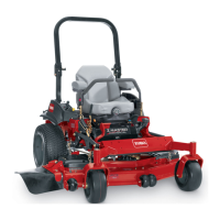
1.Holdthebladeendusingaragorthickly-padded
glove.
2.Removethebladebolt,curvedwasher,and
bladefromthespindleshaft(Figure97).
g004536
Figure97
1.Sailareaofblade3.Curvedwasher
2.Blade4.Bladebolt
SharpeningtheBlades
WARNING
Whensharpeningblades,piecesofablade
couldbethrownandcauseseriousinjury.
Wearpropereyeprotectionwhensharpening
blades.
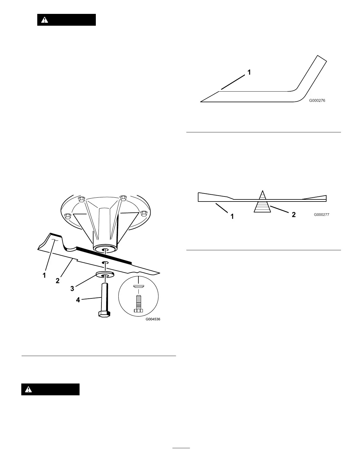
1.Usealetosharpenthecuttingedgeatboth
endsoftheblade(Figure98).Maintainthe
originalangle.Thebladeretainsitsbalanceif
thesameamountofmaterialisremovedfrom
bothcuttingedges.
g000276
Figure98
1.Sharpenatoriginalangle
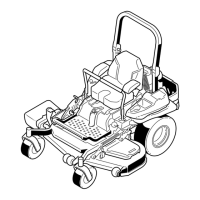
2.Checkthebalanceofthebladebyputtingiton
abladebalancer(Figure99).Ifthebladestays
inahorizontalposition,thebladeisbalanced
andcanbeused.Ifthebladeisnotbalanced,
lesomemetalofftheendofthesailareaonly
(Figure100).Repeatthisprocedureuntilthe
bladeisbalanced.
g000277
Figure99
1.Blade2.Balancer
InstallingtheBlades
1.Installthebladeontothespindleshaft(Figure
100).
Important:Thecurvedpartoftheblade
mustbepointingupwardtowardtheinside
ofthemowertoensurepropercutting.
2.Installthespringdiskandthebladebolt.The
springdiskconemustbeinstalledtowardthe
bolthead(Figure100).Torquethebladeboltto
115to150N-m(85to110ft-lb).
66