GEAR DRIVE SYSTEM
5-56 GT Series Tractors Service Manual
5
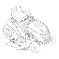
14. Install 2 hairpin cotters into the main pin (Fig. 637).
Fig 637 PICT-7682a
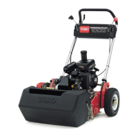
15. Install the Autodrive pedal return spring into the
notch on the speed control bracket (Fig. 638).
Fig 638 PICT-7687a
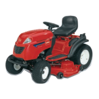
16. Install the other end of the Autodrive pedal return
spring to the tab on the frame (Fig. 639).
Fig 639 PICT-7704
17. Check the travel distance on the idler bracket (ap-
proximately 1-3/8” (3.5cm) of travel with 10 lbs.
(4.5kg) of pressure applied to the Autodrive pedal).
If additional adjustment is needed, go back to step 3
and repeat adjustment.
18. Install the mower deck. Refer to “50” Mower Deck
Installation” on page 7-8.
 Loading...