GEAR DRIVE SYSTEM
5-55GT Series Tractors Service Manual
5
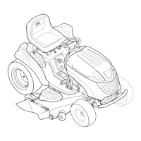
10. Loosen the jam nut on the idler adjustment rod.
Turn the idler adjustment rod clockwise or counter-
clockwise to obtain the 1-3/8” (3.5cm) idler bracket
travel (Fig. 634).
Fig 634 PICT-7693
11. Tighten the jam nut.
A. Jam nut B. Idler adjustment rod
A
B
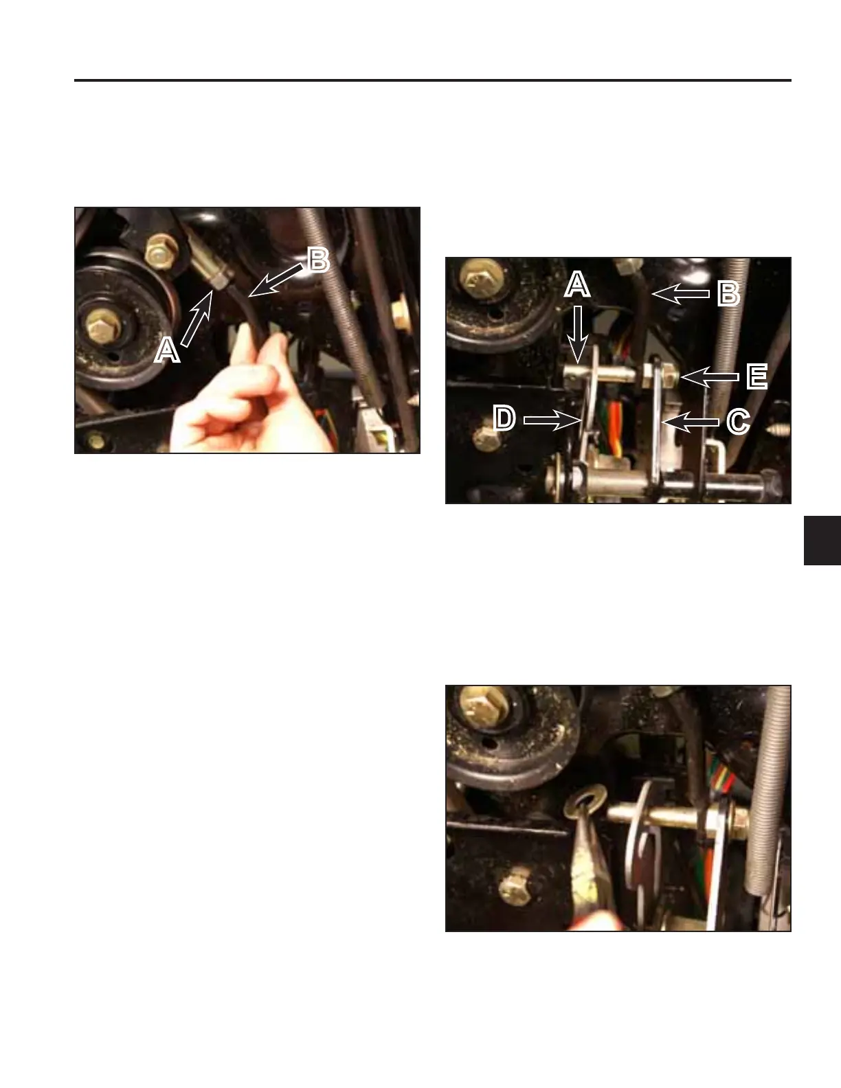
12. Install the main pin through the adjustment rod, back
into the lockout bracket, then through the speed
control assembly. Install the jam nut onto the pin
(Fig. 635).
Note: Ensure the main pin is oriented so the hairpin
holes are positioned vertically.
Fig 635 PICT-7699
13. Install a washer onto the main pin (Fig. 636).
Fig 636 PICT-7683
A. Main pin D. Speed control assembly
B. Adjustment rod E. Jam nut
C. Lockout bracket
A
B
C
D
E

 Loading...