HYDROSTATIC DRIVE SYSTEM
6-18 GT Series Tractors Service Manual
6
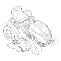
21. Position the front end of the brake control rod into
the brake control linkage (Fig. 705).
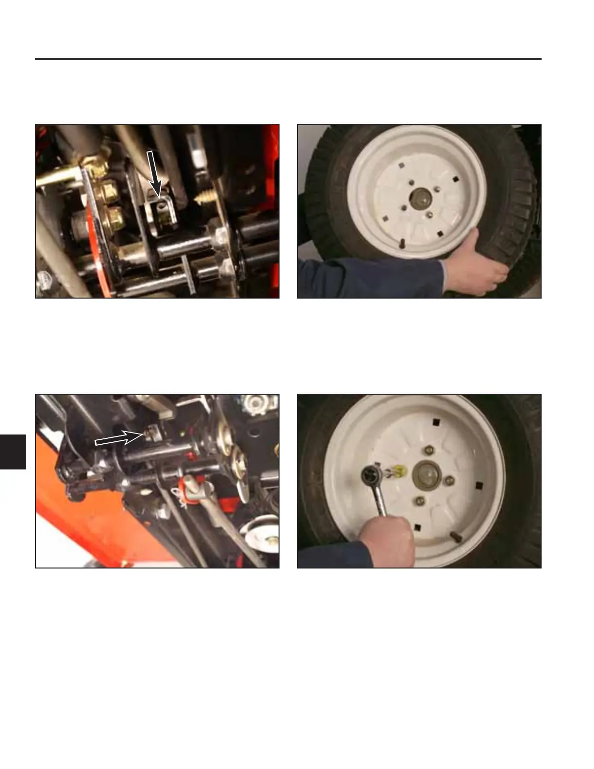
23. Slide the wheel assembly onto the wheel hub
assembly (Fig. 707).
Fig 705 PICT-7580
Fig 707 PICT-7503a
24. Install 4 lug nuts securing the wheel assembly to the
wheel hub assembly (Fig. 708).
22. Install a cotter pin securing the front end of the brake
control rod to the brake control linkage (Fig. 706).
Fig 708 PICT-7502a
Fig 706 PICT-7512

 Loading...