g231919
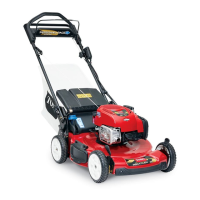
Figure123
1.Jamnut
3.Nuts(levelinglink)
2.Socket-headbolt
B.Loosenthejamnutthatsecuresthe
socket-headbolt(Figure123).
C.Adjustthewingbladeheightfortheright
sideofthedeckasfollows:
•Rotatethesocket-headboltclockwiseto
lowertherightsideofthemowerdeck.
•Turnthesocket-headbolt
counterclockwisetoraisetheright
sideofthemowerdeck.
8.Measuretheoutermostpointofthebladecutting
edges(Figure122).
9.Repeatsteps7and8untilthedifference
betweenthemeasurementsis3.2mm(1/8inch)
orless.
10.Tightenthe2nutsforthelevelinglinkandthe
jamnutforthesocket-headbolt(Figure123).
LevelingtheMowerDeckFrontto
Back
1.Adjusttheheightofcuttothe75mm(3inches)
position(Figure124).
g231943
Figure124
1.Height-of-cutindicator(75mmposition)
2.Shutofftheengineandremovethekey.
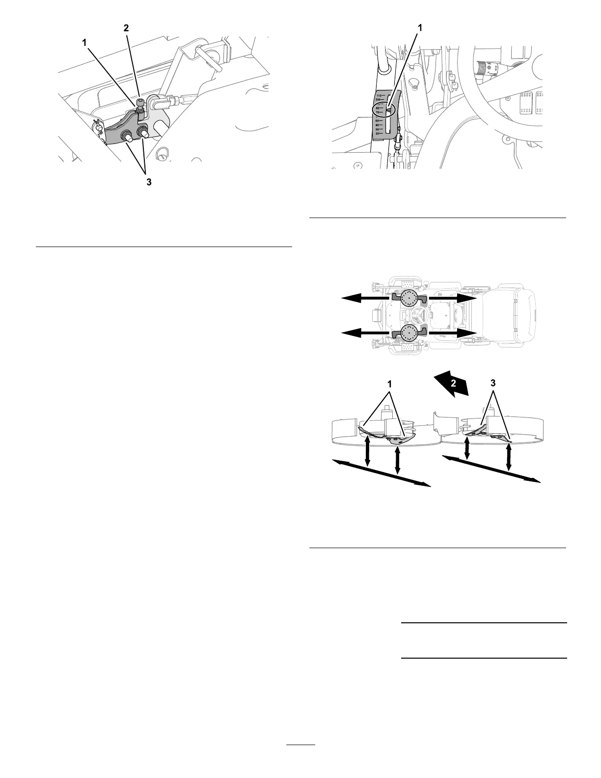
3.Alignawingbladetotheforward-mostposition
(Figure125).
g232024
g231946
Figure125
1.Rightwingblades
3.Leftwingblades
2.Frontofthemachine
4.Measurethedistancebetweenthegroundand
theforward-mostpointofthebladecuttingedge
withagaugeblock(Figure126).
Recordtheleftblade
measurementhere:
Recordtheright
blademeasurement
here:
80