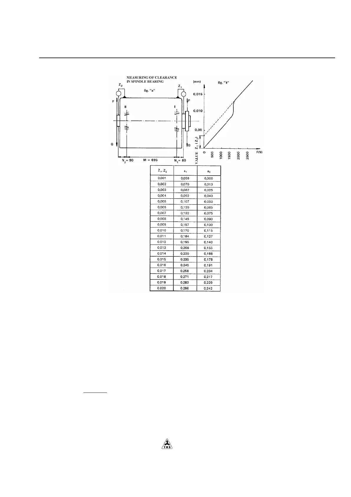
Fig. 5.5
Apply the steady force Q (ca 500 N) on the work spindle end in down vertical direction. The measuring of the change in
position of work spindle end should be taken by dial indicator in the force F acting direction and its gradual enlarging (force
F must be the same but opposite to the force Q - see fig. 5.5-a.
From the course of gradual changes of work spindle position and force F construct the diagram of bearing load analogous to
the diagram in fig. 5.5-b which the clearance ratio in measured bearing is to be read from - (values Z1 (Z2)).
Taking up the clearance (or prestress) should be done by shifting of the inner ball race of a value a1 and (a2) which can be
evaluated or read from the table in fig. 5.5.
Calculation of values a1 and (a2):
The front bearing (the mean interference value recommended 0,003)
a
1
=14 . (