Conceptional Facilities of Tailstock.
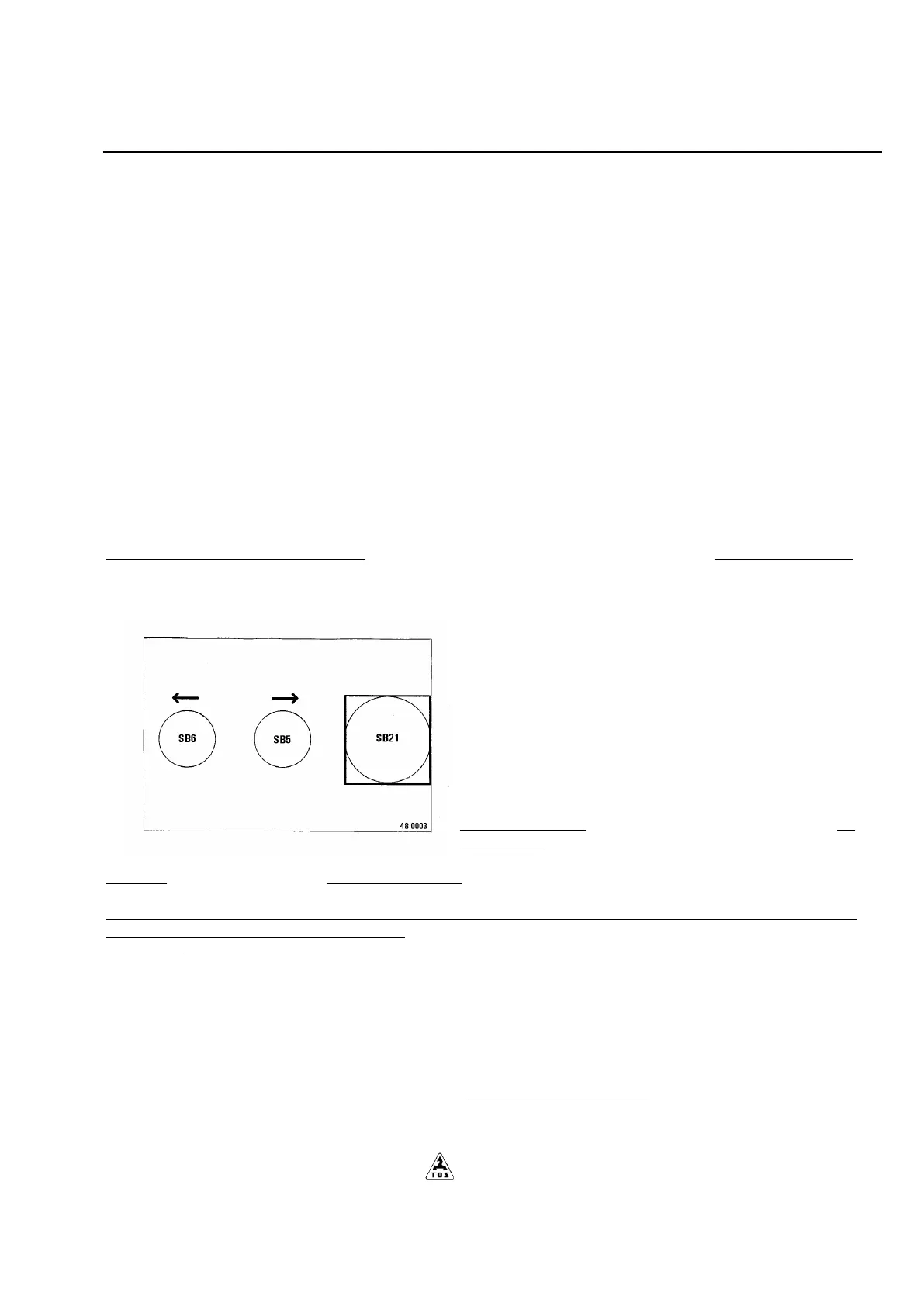
Power-operated movement of tailstock (fig. 5.6)
The mechanism of power-opreated travel permits the tailstock to be moved and controlled on bed (optional accessories):
• by pressing either push button SB 5 or SB 6 (in accordance with the sence of motion). The push buttons are located on
the the body of tailstock power - operated travel.
CAUTION: Push button SB 21 serves for emergency stop of the
machine. When used, the power - operated movement of tailstock
is cut off.
The tailstock should be locked in position on bed after its
moving by means of:
• sliding in of the pull rod 2
positioning of four holders which attach the tailstock to the bed
• tightening four nuts 1
The correct position for sliding in the pull rod is marked by an
engraved line.
In case that the tailstock position does not allow the pull rod 2 to
be slid in it is necessary to adjust it to the correct position on bed in such a way that the pawl will fit in to the casted rack on
bed.
After locking the tailstock on the bed and tightening four nuts 2 it is necessary to check all bearing surfaces of holders
against the bottom part of tailstock guideways!
WARNING:
The power - operated movement of tailstock is locked in turning.
Longitudinal movement of the tailstock sleeve is carried out by:
• operating of the hand wheel 3 through the bevel gears and screw with nut Tr 60x10.
• lock the adjusted position of the tailstock sleeve by means of screw 4 which is necessity for safe mounting of tailstock
- moment 370 N.m
The axial force applied to the centre of tailstock sleeve is taken up by three Belleville springs.These springs can
compensate a dilatability of longer workpieces which can start in turning between centres.
The intensity of the axial force picked up by the scanning device on the tailstock sleeve is possible to read on the dial
indicator located on the right-hand front tailstock side.
In tailstock version without the scanning device the springs have to be replaced by the fast ring.