EasyManua.ls Logo

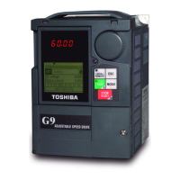
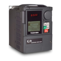
Toshiba ACE-tronics G9 ASD User Manual

Toshiba ACE-tronics G9 ASD
297 pages
To Next Page IconTo Next Page
Page #1 background imageLoading...
Page #1 background image
Document Number: 62078-000
Date: October, 2009
ACE-tronics
G9 ASD Installation and
Operation Manual
ACE-tronics G9 Adjustable Speed Drive
TOSHIBA
Buy: www.ValinOnline.com | Phone 844-385-3099 | Email: CustomerService@valin.com

Table of Contents

Questions and Answers:

Toshiba ACE-tronics G9 ASD Specifications

General IconGeneral
BrandToshiba
ModelACE-tronics G9 ASD
CategoryDC Drives
LanguageEnglish

Summary

Introduction

Important Notice

Crucial safety and legal information for equipment usage and warranty.

About This Manual

Manual’s Purpose and Scope

Defines the manual's coverage: installation, operation, maintenance, and disposal of the ASD.

General Safety Information

Safety Alert Symbol

Explains the hazard symbol indicating potential personal injury.

Signal Words

Defines DANGER, WARNING, and CAUTION signal words for hazard communication.

Special Symbols

Qualified Personnel

Specifies requirements for personnel performing installation, operation, and maintenance.

Installation Precautions

Location and Ambient Requirements

Details environmental and location criteria for ASD installation.

Mounting Requirements

Outlines necessary procedures and standards for secure ASD mounting.

Power Connections

Protection

System Integration Precautions

Personnel Protection

Focuses on safeguarding personnel from electrical and mechanical hazards.

System Setup Requirements

Operational and Maintenance Precautions

Motor Characteristics

Motor Autotuning

Describes the process of optimizing ASD performance by measuring motor parameters.

Overload Protection Adjustment

Explains how to set the ASD to protect the motor from overload conditions.

ASD Characteristics

Over-Current Protection

Details the ASD's trip behavior when design specifications are exceeded.

Using Vector Control

Explains the use of Vector Control for high torque at low speeds.

Installation and Connections

Installation Notes

Provides specific advisories and precautions for ASD installation.

Connecting the ASD

Power Connections

Covers the electrical connections for powering the ASD.

Power Connection Requirements

System Grounding

Grounding Capacitor

Explains the role and adjustment of the grounding capacitor for noise reduction.

ACE G9-120V-PCB

ACE G9-120V-PCB Precautions

Highlights critical safety warnings and handling procedures for the PCB.

Terminal Functions

Input Terminals

Describes the purpose and types of input terminals available on the PCB.

Output Terminals

Details the functionality and assignments of the analog and discrete output terminals.

Discrete Outputs

Communications

ACE G9-120V-PCB Specifications/Layout

Terminal Descriptions

Typical Connection Diagram

Startup and Test

Electronic Operator Interface

EOI Operation

Explains how to use the EOI for monitoring, inputting data, and diagnostics.

EOI Remote Mounting

Details the process and hardware for remotely mounting the EOI.

EOI Features

LCD Screen

Primary Menus of the LCD Screen

Outlines the main navigation screens: Frequency Command, Monitor, and Program.

System Operation

Operation (Local)

Describes how to turn the motor on and control it via the EOI.

Default Setting Changes

Explains how to navigate and modify parameter settings.

Startup Wizard Requirements

ASD Control Configuration

Command and Frequency Mode Control

Command Control (F003)

Defines the primary source for command input to the ASD.

Frequency Control (F004)

Override Operation

System Configuration and Menu Options

Root Menus

Explains navigation between Frequency Command, Monitor, and Program modes.

Frequency Command Mode

Details how to set the running frequency via the EOI.

EOI Command Mode

Monitor Mode

Main Monitor Selections

Program Mode Menu Navigation

Direct Access Information

Direct Access Parameters/Numbers

Lists and describes configurable parameters accessible via Direct Access.

Alarms, Trips, and Troubleshooting

Alarms and Trips

Provides information on fault conditions and system responses.

Alarms

Trips/Faults

Viewing Trip Information

Trip History

Describes how to view recorded trip information.

Clearing a Trip

Explains the essential step of clearing a trip after resolving the cause.

Enclosure Dimensions and Conduit Plate Information

Enclosure Dimensions

Current/Voltage Specifications

G9 Part Numbering Convention

Cable/Terminal/Torque Specifications

Dynamic Braking Resistor Specifications

Short Circuit Protection Recommendations

ACE-tronics G9 ASD Optional Devices

Related product manuals