2. MAJOR UNIT REPLACEMENT
EO18-33032
(Revision date: Aug., 2017)
2.1 Replacing the CPU PC Board
2-6
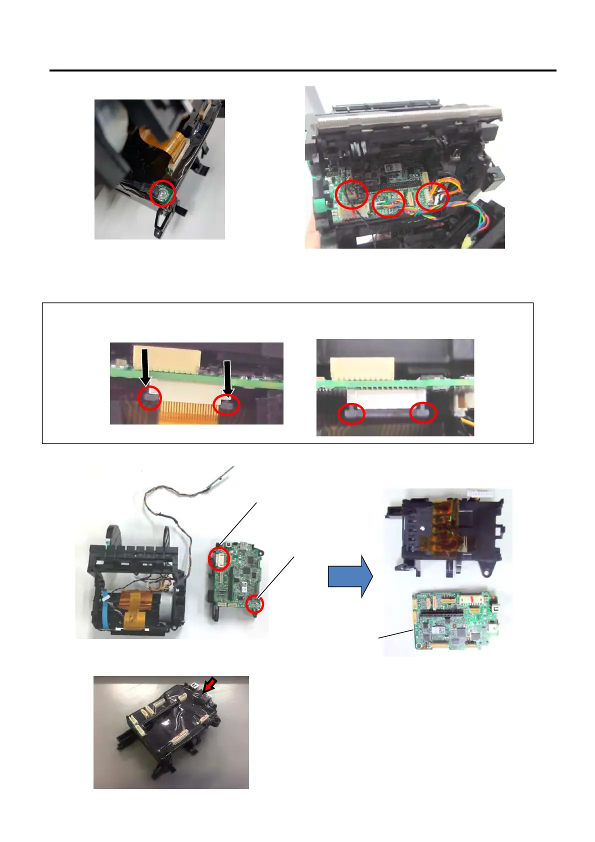
NOTE:
For this type of connector, you must first push the side locks downward to unlock in order for the flex to be
removed.
15) Remove the screw and detach the connector to take out the CPU PC Board.
For the GH model, remove the IP54 sheet from the Battery frame before removing the CPU PC Board.
Screw
CPU PC Board
Note:
Some connectors can only be detached when the
battery terminal is slightly separated from the
Function Unit.
Connector
Note:
For models with Wi-Fi Module, an additional
ground wire is screwed on the PCB as seen
on the photo. Please remove this.
 Loading...