2. MAJOR UNIT REPLACEMENT
EO18-33032
(Revision date: Aug., 2017)
2.1 Replacing the CPU PC Board
2-7
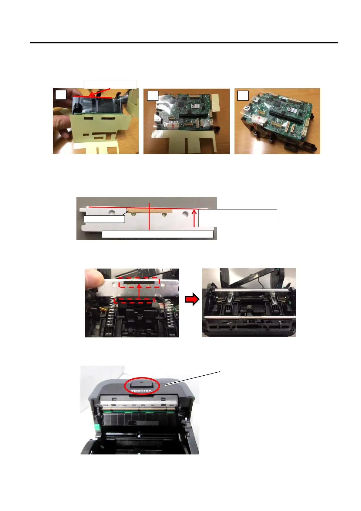
16) Replace the CPU PC Board with a new one and then reassemble the printer in the reverse order of removal.
For the GH model, attach the supplied sheet (FP3D-PCB-SHEET) in the following order after replacing the
CPU PC Board. Be careful of the orientation of the sheet. (Check the connector positions and the holes in
the sheet.)
For the GH model, attach a new adhesive tape to the back of the Thermal head assembly in the following
order.
1. Clean the back of the thermal head bracket with alcohol.
2. Attach the adhesive tape as shown in the figure below.
3. Remove the backing paper from the adhesive tape, attach the water proof sheet to the Thermal head
assembly, and mount the Thermal head assembly on the frame.
17) Return the Open cover together with the Open Cover button.
Top cover
lign the edge.
1
2
3
Adhesive tape
Align the edge of the tape
with the bracket edge.
Attach the tape at the center of the bracket.
 Loading...