2. MAJOR UNIT REPLACEMENT
EO18-33032
(Revision date: Aug., 2017)
2.5 Replacing the Print Head
2-16
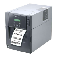
For the GH model, remove the adhesive tape from the back of the Thermal head assembly. Be sure to
completely remove the residual glue, too.
6) Replace the Print Head with a new one, then perform reassembly in the reverse order of removal.
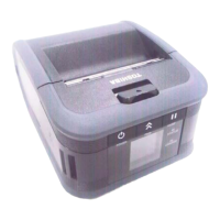
For the GH model, attach a new adhesive sheet to the Thermal head assembly in the following order.
1. Clean the back of the thermal head bracket with alcohol.
2. Attach the adhesive tape as shown in the picture below.
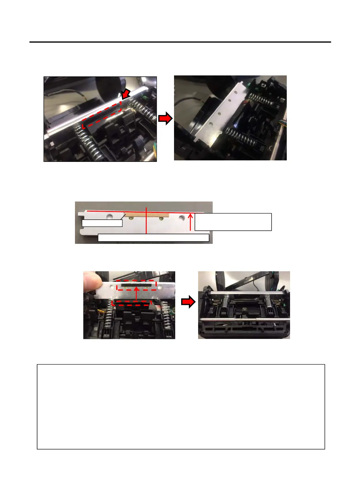
3. Remove the backing paper from the adhesive tape, attach the water proof sheet to the Thermal head
assembly, and mount the Thermal head assembly on the frame.
NOTES:
1. After replacing the Print Head, refer to the Setting Operation Manual or System Mode Manual and
perform the following operations.
Perform a RAM clear.
2. After replacing the Print Head, perform the print head broken element check and make sure none of
the elements are broken. (Refer to Section 7.6. in the System Mode Manual.)
Also perform a test print and make sure the print quality is correct. (Refer to Section 7.6 in the
System Mode Manual.) If the print tone is dark or light, perform the print tone fine adjustment. (Refer
to Section 7.5.3 in the System Mode Manual.) If the media is smudged, this may result from the
smudged print head. In the case, refer to the Owner’s Manual and clean the print head.
Align the edge of the tape
with the bracket edge.
Attach the tape at the center of the bracket.
Adhesive tape
 Loading...