3
© 2009 TOSHIBA TEC CORPORATION All rights reserved e-STUDIO205L/255/305/355/455
ADJUSTMENT
3 - 77
3.13.2 Adjusting the sensor output (Electrical system (Puncher unit;
option))
Perform the following when the punch controller PCB, horizontal registration sensor (photosensor PCB/
LED PCB), or waste full sensor (waste full photosensor PCB/waste full LED PCB) has been replaced.
<Procedure>
(1) Turn OFF the power of the equipment.
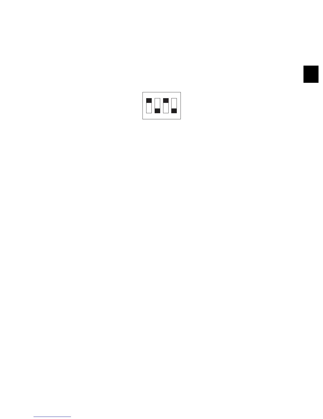
(2) Shift bits 1 through 4 on the punch controller PCB as follows:
Fig. 3-88
(3) Turn ON the power of the equipment while [0] button and [8] button are pressed simultaneously.
(4) Press SW1002 or SW1003 on the punch controller PCB. A press will automatically adjust the
sensor output.
• The adjustment is over when all LEDs on the punch controller PCB are ON: LED 1001,
LED1002, LED1003.
(5) Shift all bits of DIPSW1001 to OFF.
1234
ON

 Loading...