GENERAL DESCRIPTION
Page 13
CONTROLLER COMPARTMENT
A.
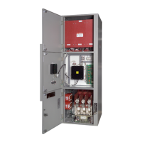
Isolation Switch (Fig. 9)
Power is switched on and off to each
individual controller compartment by a
mounted, externally-operated, three-pole
isolation switch. When the switch is in the
open position, incoming power is isolated from
the compartment interior by an automatic
shutter. Also, the load terminals of the switch
are automatically grounded in the open
position for additional safety.
The isolation switch is designed to accept a
direct connection from the line stabs of the
withdrawable contactor carriage.
This
connection is automatically made when the
contactor carriage is installed in the medium
voltage compartment.
When the switch is
closed by operating the external handle,
incoming power is applied to the line side of
the power fuses. In this position, the motor or
other load may be switched on and off by
operating the vacuum contactor.
The isolation switch
is
mechanically
interlocked with the vacuum contactor and the
compartment door. Details of the interlocking
are discussed in section H.
The position of the isolation switch blades can
be observed through a window in the medium
voltage compartment door. Thus, it is possible
to have visual evidence that the power source
is isolated before entering the medium voltage
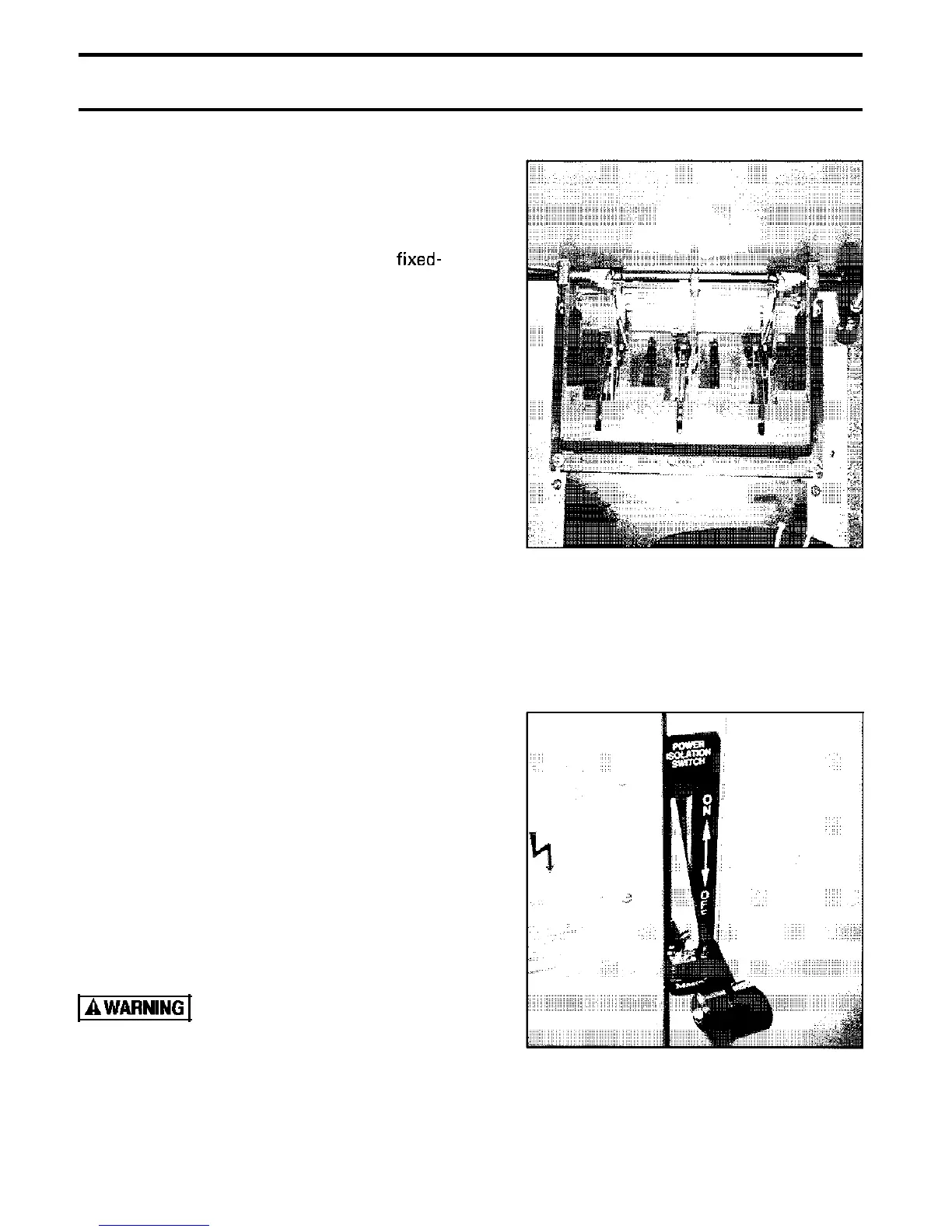
compartment. The switch is also provided
with lock-out provisions (Fig. IO).
The isolation switch has a maximum
interrupting capacity of 0.4 amperes.
Do n o t connect
additional load to the
isolation switch.
Fig. 9 Isolation Switch
Fig. 10 Isolation Switch Lockout
Phone: 800.894.0412 - Fax: 888.723.4773 - Web: www.clrwtr.com - Email: info@clrwtr.com
 Loading...


