GENERAL DESCRIPTION
Page 15
In addition, when the withdrawable contactor
carriage
is
inserted into the controller
compartment, it becomes interlocked with the
isolation switch so that the switch may not be
opened or closed unless the contacts of the
vacuum contactor are opened.
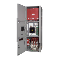
C. Service Drawer (Fig. 13)
The withdrawable contactor carriage is moved
in and out of the controller compartment on a
built-in sliding service drawer. The drawer has
four locating pins on top of it. When the
contactor carriage is placed on the drawer,
these pins engage four holes in the bottom of
the carriage which serve to align it properly.
The drawer moves in and out of the controller
compartment on sliding ball
bearing type
rails. There is a handle on the front of the
drawer to provide a gripping point.
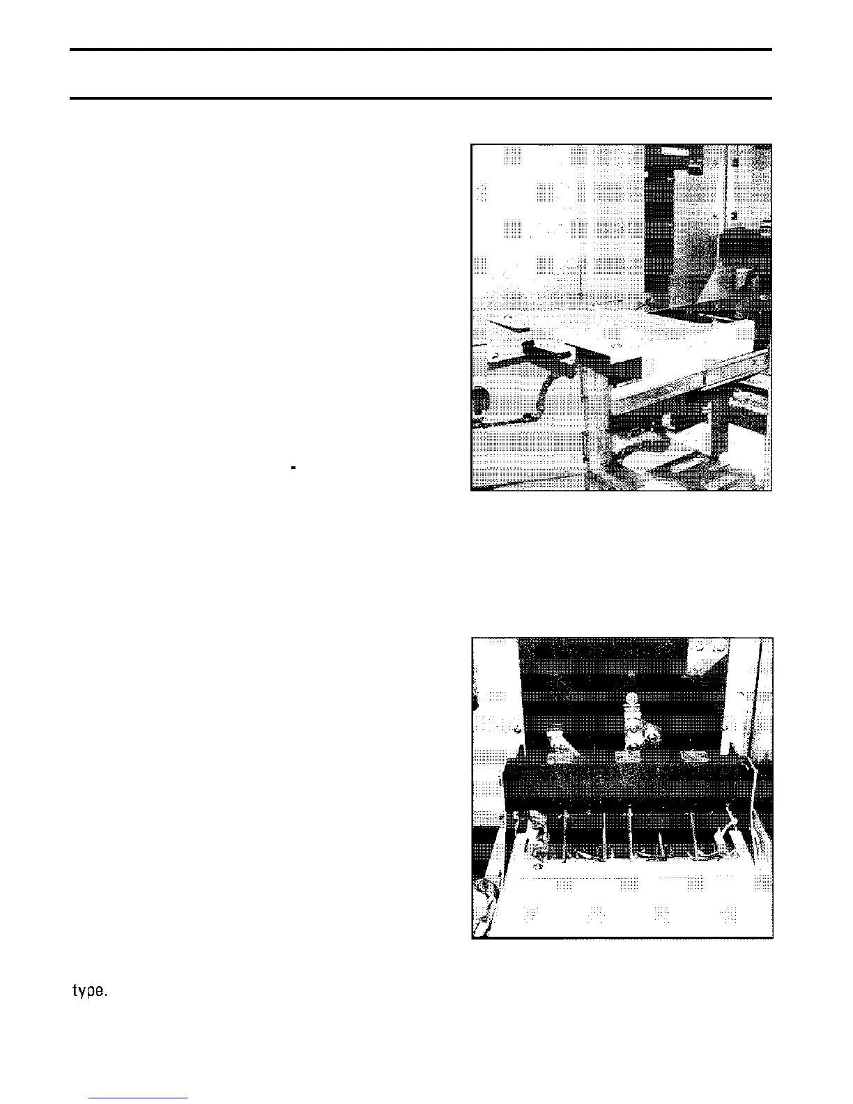
D.
Load Receptacle and Current
Transformers (Fig. 14)
The load receptacle is a fixed three-phase
disconnecting block. The vacuum contactor
load stabs on the withdrawable carriage
engage the load receptacle when the carriage
is installed in the controller compartment.
The load receptacle uses bolted pressure type
stab contacts similar to those used in the
isolation switch.
The operation of the bolted pressure contact
mechanism in the load receptacle is controlled
by a release lever located at the front of the
compartment below the service drawer.
Further details on the operation of the release
lever can be found in the OPERATION section
of this manual.
Power from the load receptacle is fed through
three current transformers located just behind
it. Current transformers furnished may be
either wound primary (bar) type, or window
Fig. 13 Service Drawer
Fig. 14 Load Receptacle
Phone: 800.894.0412 - Fax: 888.723.4773 - Web: www.clrwtr.com - Email: info@clrwtr.com
 Loading...


