Page 18
GENERAL DESCRIPTION
F.
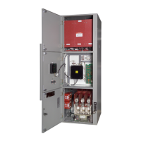
Control Power Transformer
A control power transformer (Fig. 18) is
mounted on the left-hand side wall of the
controller compartment. Power is supplied to
the fused primary of the control power
transformer from stabs on the withdrawable
contactor carriage. These stabs engage clips
on the transformer when the carriage is
inserted into the compartment.
Optionally, a second transformer (Fig.
normally used as an instrument transformer,
can be mounted in the compartment. When
this option is supplied, a third set of stabs is
furnished on the withdrawable carriage. The
two transformers are then connected in an
open-delta arrangement.
Another option sometimes supplied is a second
control power transformer connected in parallel
with the first to increase the available KVA
capacity.
Both the control and optional potential
transformer are used to supply power to the
low voltage circuits of the controller. This
includes power for the vacuum contactor
operating coil and for various instrumentation.
An electrical interlock is provided to ensure
that all load is disconnected from the control
power transformer secondary winding before
the power isolation switch can be opened or
closed.
Fig. 18 Control Power Transformer
Fig. 19 Optional Transformer
Phone: 800.894.0412 - Fax: 888.723.4773 - Web: www.clrwtr.com - Email: info@clrwtr.com
 Loading...


