GENERAL DESCRIPTION Page 21
I.
Interlocks Electrical
a.
Control Power Interlock
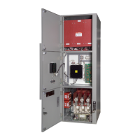
The control power interlock is a
microswitch which is directly driven by the
operation of the switch handle (Fig. 24). This
normally open switch is closed only when the
handle is fully ON.
It ensures that all load is
disconnected from the control power
transformer secondary winding before the
isolation switch can be operated.
As the switch handle is moved from ON to
OFF, the CPI opens before the main contacts
of the power isolation switch. Conversely,
during closing of the switch, the CPI contacts
do not close until the switch contacts have
fully closed. The isolation switch is therefore
only subjected to making and breaking currents
equal to the no-load magnetizing current of the
transformer.
Do not connect any
additional load to the
isolation switch.
b.
Test Power Interlock
The test power interlock is a scheme
provided to allow simulated operation of the
controller from a separate control power (test)
source with power removed from the medium
voltage circuit. During normal controller
operation with the isolation switch closed,
control power is fed from the control
transformer secondary to a receptacle mounted
on the low voltage
(Fig. 25). A plug,
inserted into this receptacle, supplies power to
the controller’s low voltage compartment.
For testing purposes, the isolation switch must
be turned off and the controller door must be
opened. The plug is then removed and
inserted into an ordinary extension cord.
Plugging the extension cord into a conventional
outlet provides
power for performing
control circuit operational tests while the
medium voltage circuit is de-energized.
Fig. 24 Control Power Interlock
Fig. 25 Test Power Receptacle
Phone: 800.894.0412 - Fax: 888.723.4773 - Web: www.clrwtr.com - Email: info@clrwtr.com
 Loading...


