INSTALLATION
Page 33
INCOMING LINE
Incoming power cable connections should be
made at the points shown on the wiring
diagram furnished with the equipment. These
connections will normally be made in a
separate incoming compartment to bus lugs or
to an incoming load interrupter switch or
vacuum circuit breaker.
OUTGOING LOAD
Outgoing load connections are made in each
controller compartment at the points shown in
Fig. 15 through Fig. 17.
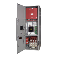
The load cables should be routed through the
furnished within the enclosure.
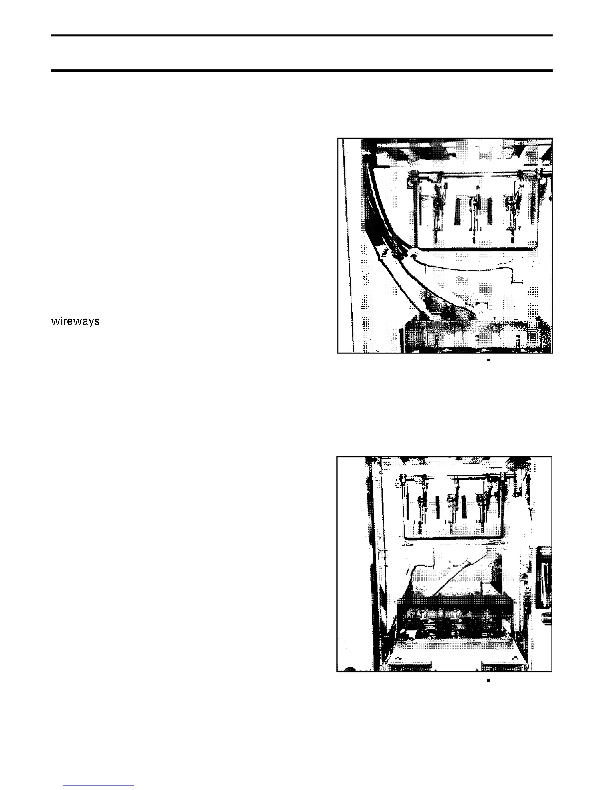
Typical routing of load cables for a two-high
controller arrangement is depicted in Fig. 37
and Fig. 38 for both top and bottom entry of
cables.
Load cable termination arrangments for certain
controllers such as reduced
voltage
autotransformer types may differ from those
shown in this manual. In these cases refer to
the drawings furnished with the equipment.
Fig. 37 Controller Load Wiring
Top Entry
Fig. 38 Controller Load Wiring
Bottom Entry
Phone: 800.894.0412 - Fax: 888.723.4773 - Web: www.clrwtr.com - Email: info@clrwtr.com
 Loading...


