E6581528
H-12
8
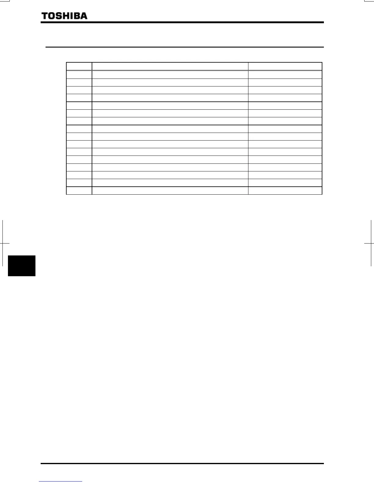
8.5 Display of alarm, pre-alarm, etc.
When the inverter alarm, pre-alarm, etc. occurred, the contents are displayed. (Some are not displayed.)
Listed below ones can be monitored via communication (FC91). Refer to 13.1 for the other alarms.
Bit Description Panel indication
0 Overcurrent pre-alarm
1 Inverter overload pre-alarm
2 Motor overload pre-alarm
3 Overheat pre-alarm
4 Overvoltage pre-alarm achieving PBR operation level
5 Main circuit undervoltage detected
6 (Reservation area)
-
7 Low current alarm
-
8 Overtorque pre-alarm
-
9 Braking resistor overload pre-alarm
-
10 Cumulative operation time alarm
-
11 PROFIBUS/DeviceNet/CC-Link communication error
12 RS485 communication error
13 (Reservation area)
-
14 Forced deceleration stop because of a momentary power failure
15 Pre-alarm stop because of prolonged lower-limit frequency operation
Note: For each bit, “0” indicates normal condition and “1” indicates appearance of alarm, etc.

 Loading...


