E6581528
B-10
2
2.3 Description of terminals
2.3.1 Main circuit terminals
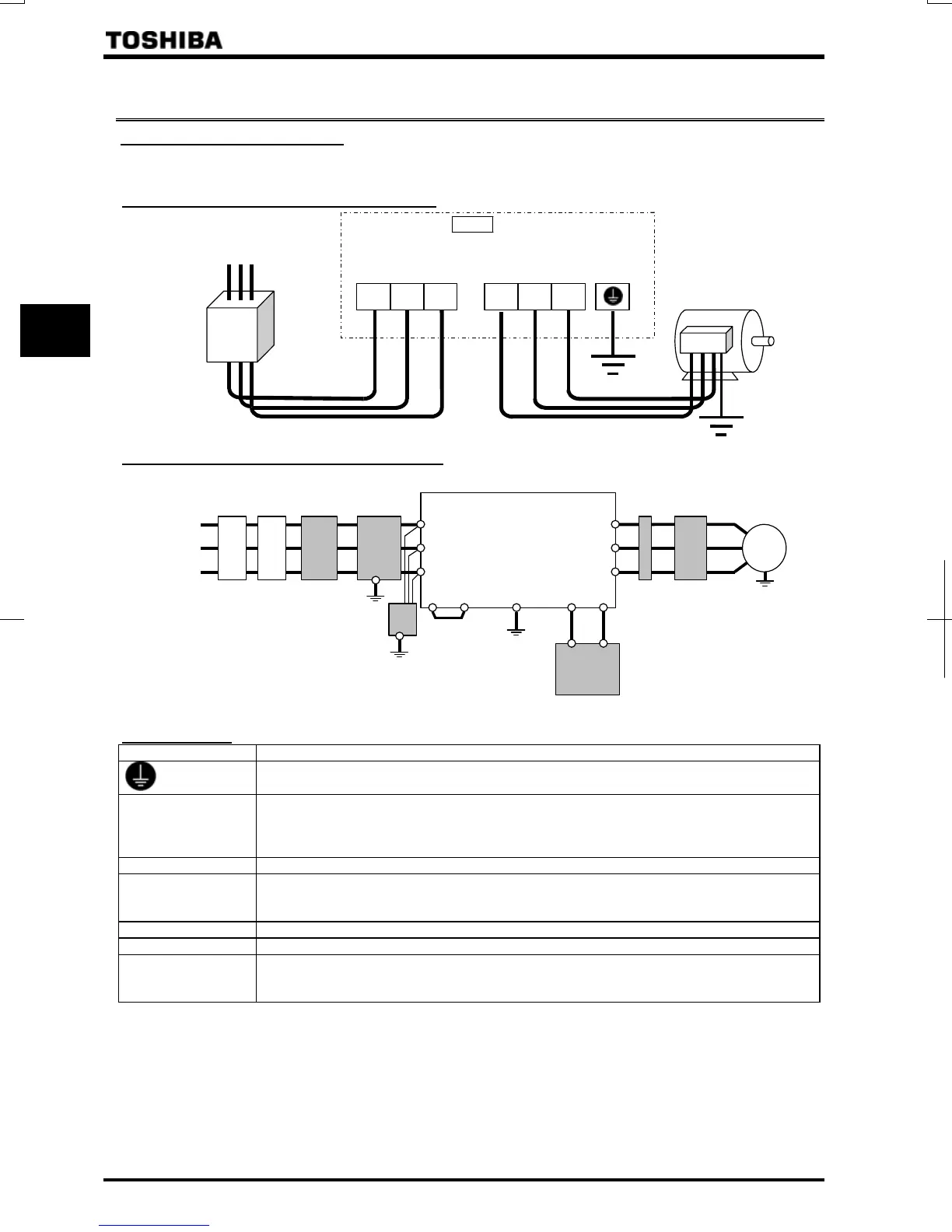
This diagram shows an example of wiring of the main circuit. Use options if necessary.
Power supply and motor connections
Power supply
S/L2 T/L3
Motor
No-fuse
breaker
Connect the power
cables to RL1, S/L2,
and T/L3.
Connect the motor
cables to U/T1, V/T2
and W/T3.
VF-AS1
E
U/T1 V/T2 W/T3R/L1
Connection with peripheral equipment
Motor
Zero-phase
reactor
Power
supply
Inverter
Braking resistor [Note]
Surge
su
ressin
filter
Simplified
radio noise
filter
High-attenuation
radio noise
reduction filter
Input AC
reactor
Magnetic
contactor
No-fuse
breaker
R/L1
S/L2
T/L3
PA/+ P0
PA
PB
V/T2
U/T1
W/T3
IM
Note: Connect a braking unit
between the terminals PA/+
and PC/-, if necessary.
Main circuit
Terminal symbol Terminal function
Grounding terminal for inverter casing
R/L1, S/L2, T/L3
(R/L1.1, S/L2.1, T/L3.1,
R/L1.2, S/L2.2, T/L3.2)
*1
Power input terminal
VFAS1-5015PM~5075PM: VFAS1-6022PL~6630KPC:
Three-phase 500~600V-50/60Hz Three-phase 500~690V-50Hz/60Hz
U/T1, V/T2, W/T3 Connect to a (3-phase induction) motor.
PA/+, PB
(PA, PB) *2
Connect a braking resistor.
Change the parameters , and if necessary.
200kW models and larger are not equipped with terminal PB.
PC/- This is a negative potential terminal in the internal DC main circuit.
PO, PA/+ Shorted by a short bar when shipped from the factory (90kW or smaller).
RO, SO, TO
VFAS1-6110KPC or larger
Inverter’s cooling fan power input terminals. Don’t need to connect if you use TRS.
(TRS: Transformer for fan supply)
*1: Value in ( ) VFAS1-6400KPC to 6630KPC.
*2: Value in ( ) VFAS1-6110KPC to 6160KPC.

 Loading...


