E6581528
B-11
2
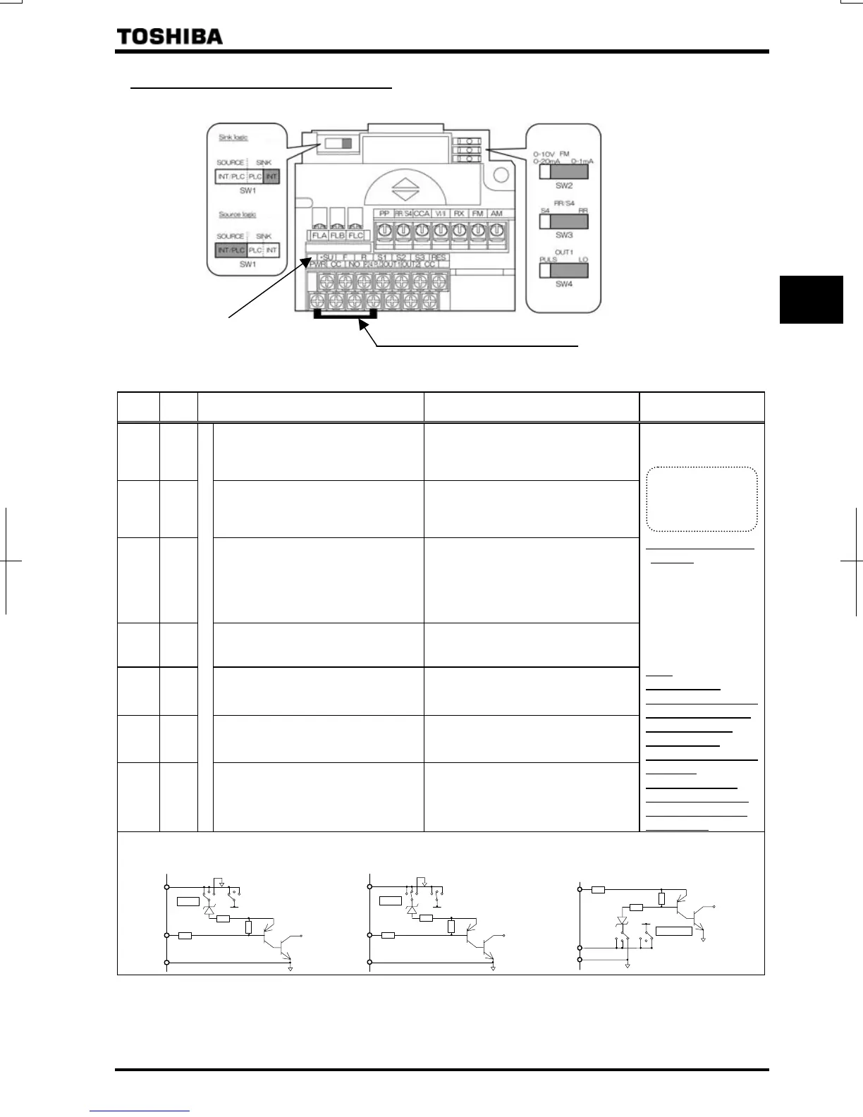
2.3.2 Control circuit terminal block
The control circuit terminal block is common to all equipment.
PWR-P24/PLC Shorting bar
Color of a label is yellow.
VFAS1-*****-WN,HN
⇒ How to set input terminal function, refer to section 7.
Terminal
symbol
Input/
output
Function (Sink logic)
VFAS1-****-WN, HN
Function (Source logic) Electrical specifications
F Input
Shorting across F-CC causes forward
rotation; open causes deceleration
stop. (Across PWR-P24/PLC is short
state.)
Shorting across F-P24/PLC causes
forward rotation; open causes
deceleration stop.
R Input
Shorting across R-CC causes reverse
rotation; open causes deceleration
stop. (Across PWR-P24/PLC is short
state.)
Shorting across R-P24/PLC causes
reverse rotation; open causes
deceleration stop.
RES Input
Shorting and then opening RES-CC
cancels the status held by an inverter
protective function. When the inverter
is operating normally, shorting and
then opening RES-CC produces no
effect.
Shorting and then opening RES-
P24/PLC cancels the status held by an
inverter protective function. When the
inverter is operating normally, shorting
and then opening RES-P24/PLC
produces no effect.
S1 Input
Shorting across S1-CC causes preset
speed operation.
Shorting across S1-P24/PLC causes
preset speed operation.
S2 Input
Shorting across S2-CC causes preset
speed operation.
Shorting across S2-P24/PLC causes
preset speed operation.
S3 Input
Shorting across S3-CC causes preset
speed operation.
Shorting across S3-P24/PLC causes
preset speed operation.
RR/S4 Input
Multifunction programmable contact input
SW3: When SW3 is in the S4 position,
S4 and CC are shorted and preset
speed operation is selected.
SW3: When SW3 is in the S4 position,
S4 and P24/PLC are shorted and preset
speed operation is selected.
Voltage free contact
input
24Vdc-5mA or less
*Sink/source selectable
with SW1
Sink input
ON:
Less than DC10V
OFF:DC16V or more
Source input
ON:DC11V or more
OFF:
Less than DC5V
Note:
Even when an
external power supply
is used (in sink logic
mode, i.e., when
SINK (PLC) is
selected), connect the
reference
potential-side (0V
side) cable from the
power supply to the
CC terminal.
SW1=SINK (INT): Sink logic (When the
internal 24V power supply is used)
2.2kΩ
P24/PLC
CC
2.2kΩ
P24
SINK
SOURCE
SW1
SW1=SINK (PLC): Sink logic (When an
external 24V power supply is used)
SW1=SOURCE (INT/PLC):
Source logic (When the internal 24V
power supply or an external 24V power
supply is used)
If SW1 is set to 1
If SW1 is set to 2
If SW1 is set to 3
2.2k
CC
2.2k
P24
SINK
SOURCE
SW1
CC
SOURCE
2.2k
P24/PLC
2.2k
P24
SINK
SW1
P24/PLC
Lan current signal.
Choose low
current contacts to
avoid
oor

 Loading...


