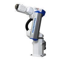
TRANSPORTATION AND INSTALLATION MANUAL
8
4.3. Installation surface dimensions ........................................................................... 57
4.4. Cautions for assembling the control panel .......................................................... 58
5. Installing the Controller (In case of TSL3100E) ............................................. 61
5.1. External Dimensions ........................................................................................... 61
5.2. Precautions for Direct Installation ....................................................................... 62
5.3. Installation surface dimensions ........................................................................... 63
5.4. Cautions for assembling the control panel .......................................................... 64
6. Installing the Controller (In case of TS3100) ................................................. 66
6.1. External Dimensions ........................................................................................... 66
6.2. Precautions for Direct Installation ....................................................................... 67
6.3. Installation surface dimensions ........................................................................... 68
6.4. Precautions for Rack Mounting ........................................................................... 68
7. System Connections(In case of TSL3100) .................................................... 71
7.1. Cable Wiring ....................................................................................................... 71
Connector Arrangement on the Controller ................................................ 71 7.1.1.
Connecting the Power Cable “ACIN” ([1] of Fig. 7.1; plug connector 7.1.2.
attached) ............................................................................................................... 72
Connecting the Motor Cable/Encoder Cable ............................................ 74 7.1.3.
Connecting the Brake Cable/Robot Control Signal Cable ........................ 75 7.1.4.
Connecting Power Supply Cable for External Input/Output "GND, P24V" 7.1.5.
([6] in Fig. 7.1) ....................................................................................................... 75
Connecting and Disconnecting Cables ..................................................... 76 7.1.6.
Examples of Connector Terminal Arrangement (for the TSL3100) ........... 78 7.1.7.
7.2. Controller Connector Signals .............................................................................. 82
Connector Signal Connection Diagrams ................................................... 82 7.2.1.
Jumpers for Safety Related Signals ......................................................... 82 7.2.2.
8. System Connections (In case of TSL3100E) ................................................. 84
8.1. Cable Wiring ....................................................................................................... 84
Connector Arrangement on the Controller ................................................ 84 8.1.1.
Connecting the Power Cable “ACIN” ([1] of Fig. 8.1; plug connector
8.1.2.
attached) ............................................................................................................... 85
Connecting the Motor Cable/Encoder Cable ............................................ 87 8.1.3.
Connecting the Brake Cable/Robot Control Signal Cable ........................ 88 8.1.4.
Connecting Power Supply Cable for External Input/Output "GND, P24V" 8.1.5.
([6] in Fig. 8.1) ....................................................................................................... 88
Connecting and Disconnecting Cables ..................................................... 89 8.1.6.
Examples of Connector Terminal Arrangement (for the TSL3100) ........... 92 8.1.7.
8.2. Controller Connector Signals .............................................................................. 95

 Loading...