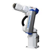
TRANSPORTATION AND INSTALLATION MANUAL
9
Connector Signal Connection Diagrams ................................................... 95
8.2.1.
Jumpers for Safety Related Signals ......................................................... 95 8.2.2.
9. System Connections(In case of TS3100) ...................................................... 97
9.1. Cable Wiring ....................................................................................................... 97
Connector Arrangement on the Controller ................................................ 97 9.1.1.
Connecting the Power Cable “ACIN” ([1] of Fig. 9.1; plug connector 9.1.2.
attached) ............................................................................................................... 98
Connecting the Motor Cable/Encoder Cable ............................................ 99 9.1.3.
Connecting the Brake Cable/Robot Control Signal Cable ........................ 99 9.1.4.
Connecting Power Supply Cable for External Input/Output "GND, P24V" 9.1.5.
([8] in Fig. 9.1 ...................................................................................................... 100
Connecting and Disconnecting Cables ................................................... 102 9.1.6.
Examples of Connector Terminal Arrangement (for the TS3100) ........... 104 9.1.7.
9.2. Controller Connector Signals (for the TS3100) ................................................. 107
Connector Signal Connection Diagrams ................................................. 107 9.2.1.
Jumpers for Safety Related Signals ....................................................... 107 9.2.2.
9.3. When Detaching the Control Panel from the Controller (for the TS3100) ......... 109
Dismounting the Control Panel ............................................................... 109 9.3.1.
Cables between the Controller and the Control Panel ............................ 109 9.3.2.
Installation Dimensions of the Control Panel .......................................... 110 9.3.3.
Mounting the Dummy Panel to the Controller ......................................... 111 9.3.4.
Dimensions When the Control Panel Is Detached .................................. 112 9.3.5.
10. Tool Interface (Robot Body Side) ................................................................ 113
10.1. Mounting Tool ................................................................................................... 113
10.2. Tool Air Piping ................................................................................................... 114
10.3. Permissible Load Conditions and Program Setting ........................................... 116
Permissible Load Conditions .................................................................. 116 10.3.1.
Load Conditions and Program Setting .................................................... 118 10.3.2.
11. Tool Interface (for the TSL 3100) ................................................................ 121
11.1. Tool wiring ......................................................................................................... 121
Tool Signals (Controller Side) ................................................................. 121 11.1.1.
Tool Wiring (Robot Arm Side) ................................................................. 125 11.1.2.
12. Tool Interface (for the TSL3100E) ............................................................... 132
12.1. Tool wiring ......................................................................................................... 132
Tool Signals (Controller Side) ................................................................. 132 12.1.1.
Tool Wiring (Robot Arm Side) ................................................................. 136 12.1.2.
13. Tool Interface (for the TS3100) ................................................................... 143

 Loading...