CG-SVX17D-EN 69
Installation - Mechanical
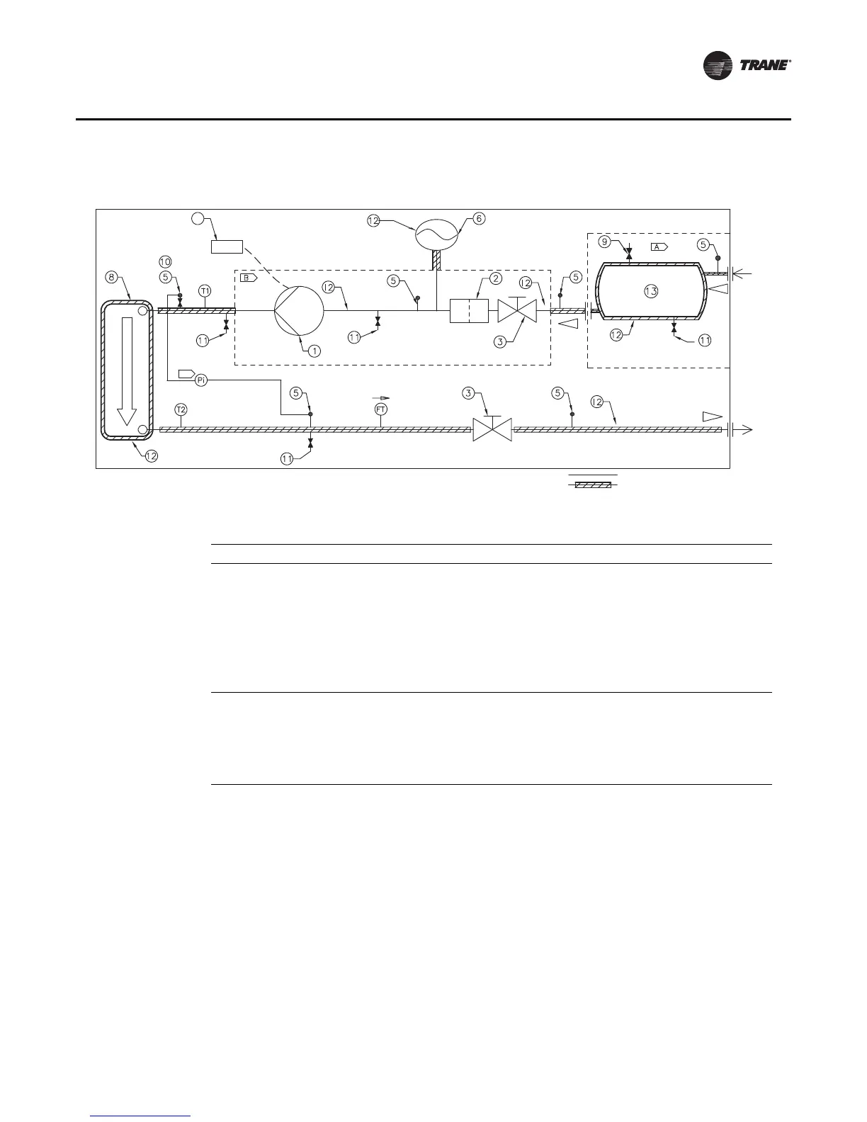
Figure 56. Pump package unit schematic
Water Line
Insulated Water Line
4
C
CONNECTIONS TO UNIT
INLET
OUTLET
Table 27. Pump package components
Item Description Item Description
1 Centrifugal Pump 8 Evaporator heat exchanger
2 Water Strainer 9 Automatic Air Vent
3 Butterfly Valve 10 Manual Air Bleed
4 Inverter 11 Drain Valve
5 Valve for Pressure Point 12 Water Heater
6 Expansion Tank 13 Buffer Tank (Optional)
7n/a
Pi Gauge A Optional Buffer Tank
FT Water Flow Switch B Insulated Pump Box
T1 Evap Water Inlet Temp Sensor
C
Brazed plate differential pressure gauge and
piping not supplied. Must account for water
head height difference when calculating
brazed plate pressure differential.
T2 Evap Water Outlet Temp Sensor