RT-SVX24Q-EN
159
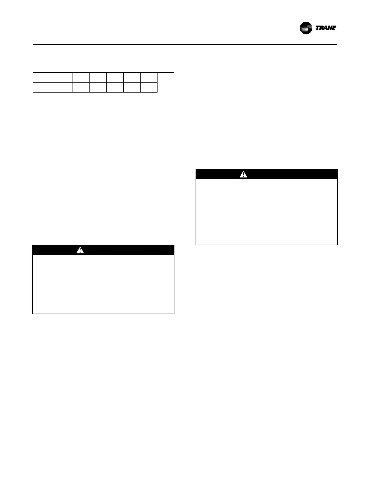
Table 55. Standard unit (no ERW) (economizer)
outside air damper travel adjustment/pressure drop
(inches w.c.) (continued)
25,000
0.37 0.45 0.69 0.92 1.24
23,000
0.31 0.37 0.57 0.76 1.04
Standard Unit with Energy Recovery
Wheel
Economizer Damper Adjustment - ERW units
Outside & Return Air Damper Operation
The outside air and return air damper actuators are
accessible through from the filter section of the unit.
The outside air and return air dampers have individual
actuators that are linked electronically. The actuators
are preset to 0 degrees from the factory. Refer to
“Table 46, p. 170,” for the appropriate actuator position
for the unit and operating airflow (CFM).
To Adjust the Outside Air Damper Travel
1. Drill a 1/4" hole through the unit casing up stream
of the return air dampers and below the energy
recovery wheel. Use a location that will produce an
accurate reading with the least amount of
turbulence. Several locations may be necessary,
and average the reading.
WWAARRNNIINNGG
HHaazzaarrddoouuss VVoollttaaggee!!
FFaaiilluurree ttoo ddiissccoonnnneecctt ppoowweerr bbeeffoorree sseerrvviicciinngg ccoouulldd
rreessuulltt iinn ddeeaatthh oorr sseerriioouuss iinnjjuurryy..
DDiissccoonnnneecctt aallll eelleeccttrriicc ppoowweerr,, iinncclluuddiinngg rreemmoottee
ddiissccoonnnneeccttss bbeeffoorree sseerrvviicciinngg.. FFoollllooww pprrooppeerr
lloocckkoouutt//ttaaggoouutt pprroocceedduurreess ttoo eennssuurree tthhee ppoowweerr
ccaann nnoott bbee iinnaaddvveerrtteennttllyy eenneerrggiizzeedd.. VVeerriiffyy tthhaatt nnoo
ppoowweerr iiss pprreesseenntt wwiitthh aa vvoollttmmeetteerr..
IImmppoorrttaanntt:: HIGH VOLTAGE IS PRESENT AT
TERMINAL BLOCK OR UNIT
DISCONNECT SWITCH.
2. Close the disconnect switch or circuit protector
switch that provides the supply power to the unit
terminal block or the unit mounted disconnect
switch.
3. Turn the 115 volt control circuit switch and the 24
volt control circuit switch to the “On” position.
4. Open the Human Interface access door, located in
the unit control panel, and press the SERVICE
MODE key to display the first service screen. Refer
to the latest edition of the applicable programming
manual for applications for the SERVICE TEST
screens and programming instructions.
5. Use to program the following system components
for operation by scrolling through the displays:
Supply Fan (On)
VFD Cmd (100%, if applicable)
RTM Occ/Unocc Output
(Unoccupied)
OA Damper Pos (0%)
Outside Air Bypass Damper Pos (0%)
Exhaust Air Bypass Damper Pos (0%)
6. Once the configuration for the components is
complete, press the NEXT key until the LCD
displays the “Start test in __Sec." screen. Press the
+ key to designate the delay before the test is to
start. This service test will begin after the TEST
START key is pressed and the delay designated in
this step has elapsed. Press the ENTER key to
confirm this choice.
WWAARRNNIINNGG
RRoottaattiinngg CCoommppoonneennttss!!
FFaaiilluurree ttoo ddiissccoonnnneecctt ppoowweerr bbeeffoorree sseerrvviicciinngg ccoouulldd
rreessuulltt iinn rroottaattiinngg ccoommppoonneennttss ccuuttttiinngg aanndd ssllaasshhiinngg
tteecchhnniicciiaann wwhhiicchh ccoouulldd rreessuulltt iinn ddeeaatthh oorr sseerriioouuss
iinnjjuurryy..
DDiissccoonnnneecctt aallll eelleeccttrriicc ppoowweerr,, iinncclluuddiinngg rreemmoottee
ddiissccoonnnneeccttss bbeeffoorree sseerrvviicciinngg.. FFoollllooww pprrooppeerr
lloocckkoouutt//ttaaggoouutt pprroocceedduurreess ttoo eennssuurree tthhee ppoowweerr
ccaann nnoott bbee iinnaaddvveerrtteennttllyy eenneerrggiizzeedd..
7. Press the TEST START key to start the test.
Remember that the delay designated in step 6 must
elapse before the fan will begin to operate.
8. With the outside air dampers fully closed and the
supply fan operating at 100% airflow requirements,
measure the return static pressure at the location
determined in step 1.
9. Press the STOP key at the Human Interface Module
in the unit control panel to stop the fan operation.
10. Open the field supplied main power disconnect
switch upstream of the rooftop unit. Lock the
disconnect switch in the “Open” position while
working on the dampers.
11. Locate the static pressure reading in “Table 46,
p. 170,” and determine which damper needs to be
adjusted and the degree reading. Proceed to the
appropriate damper actuator procedure.
To Adjust the Outside Air Damper Actuators
1. Remove the shaft coupling from the damper shaft
by loosening the bolt and removing the retainer
clip. Be careful not to rotate the shaft.
2. Position the shaft coupling so that the indicator
points to the degree value obtained from Step 11.
The shaft coupling is adjustable in 5 degree
increments.
3. Replace the retainer clip and tighten the shaft
coupling on the shaft (120-180 in-lbs).
UUnniitt SSttaarrttuupp

 Loading...


