202
RT-SVX24Q-EN
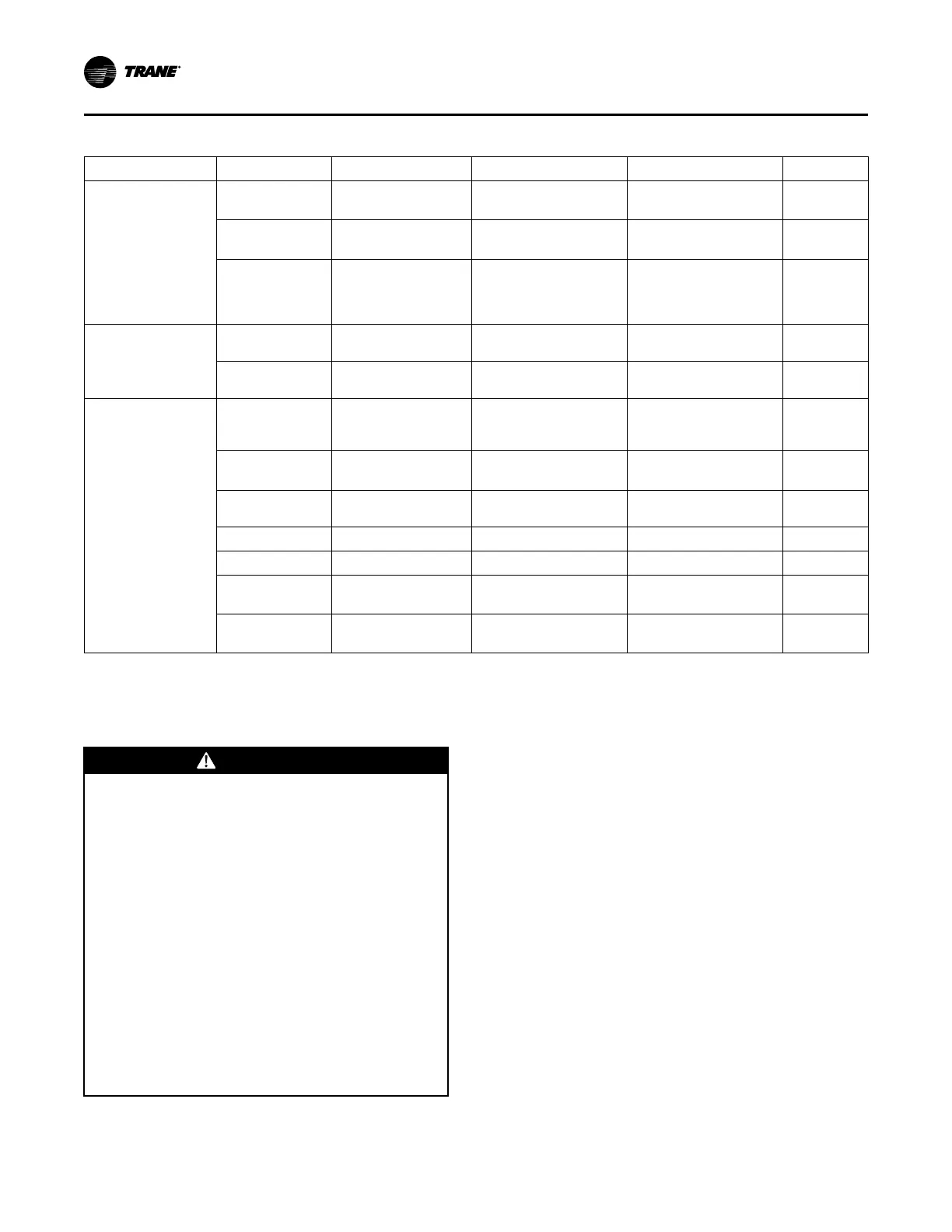
Table 77. Supply and exhaust/return fan VFD programming parameters (continued)
Menu ID Name FC DDP Unit
Digital In/Out
5-12
Terminal 27 Digital
Input
Coast inverse Coast inverse
5-13
Terminal 29 Digital
Input
No operation No operation
5-40
Function Relay
Relay 1 active No alarm,
Relay 2 active Motor
Running (Relay 1 [160],
Relay 2 [5])
Relay 1 active No alarm,
Relay 2 active Motor
Running (Relay 1 [160],
Relay 2 [5])
Analog In/Out
6-14
Terminal 53 Low Ref./
Feedb. Value
22 15
6-15
Terminal 53 High Ref./
Feedb. Value
60 83
Special Function
14-01
Switching Frequency
8.0 kHz (drive dependant,
set to 5kHz if 8kHz not
available)
8.0 kHz (drive dependant,
set to 5kHz if 8kHz not
available)
14-11 (TR200
only)
Mains Voltage at Mains
Fault
400V for 460V 60Hz unit,
leave at default otherwise
400V for 460V 60Hz unit,
leave at default otherwise
14-12
Function at Mains
Imbalance
Derate Derate
14-20 Reset Mode Automatic reset x 5 Automatic reset x 5
14-50 RFI Filter Off Off
14-60 (TR200
only)
Function at Over
Temperature
Derate Derate
14-61 (TR200
only)
Function at Inverter
Overload
Derate Derate
Note: For 50Hz units parameters 0-06 Grid Type (TR150s only) and 1-23 Motor Freq will need to be set accordingly.
eFlex™ Compressor VFD Programming
Parameters
WWAARRNNIINNGG
HHaazzaarrddoouuss VVoollttaaggee ww//CCaappaacciittoorrss!!
FFaaiilluurree ttoo ddiissccoonnnneecctt ppoowweerr aanndd ddiisscchhaarrggee
ccaappaacciittoorrss bbeeffoorree sseerrvviicciinngg ccoouulldd rreessuulltt iinn ddeeaatthh oorr
sseerriioouuss iinnjjuurryy..
DDiissccoonnnneecctt aallll eelleeccttrriicc ppoowweerr,, iinncclluuddiinngg rreemmoottee
ddiissccoonnnneeccttss aanndd ddiisscchhaarrggee aallll mmoottoorr ssttaarrtt//rruunn
ccaappaacciittoorrss bbeeffoorree sseerrvviicciinngg.. FFoollllooww pprrooppeerr
lloocckkoouutt//ttaaggoouutt pprroocceedduurreess ttoo eennssuurree tthhee ppoowweerr
ccaannnnoott bbee iinnaaddvveerrtteennttllyy eenneerrggiizzeedd.. FFoorr vvaarriiaabbllee
ffrreeqquueennccyy ddrriivveess oorr ootthheerr eenneerrggyy ssttoorriinngg
ccoommppoonneennttss pprroovviiddeedd bbyy TTrraannee oorr ootthheerrss,, rreeffeerr ttoo
tthhee aapppprroopprriiaattee mmaannuuffaaccttuurreerr’’ss lliitteerraattuurree ffoorr
aalllloowwaabbllee wwaaiittiinngg ppeerriiooddss ffoorr ddiisscchhaarrggee ooff
ccaappaacciittoorrss.. VVeerriiffyy wwiitthh aa CCAATT IIIIII oorr IIVV vvoollttmmeetteerr
rraatteedd ppeerr NNFFPPAA 7700EE tthhaatt aallll ccaappaacciittoorrss hhaavvee
ddiisscchhaarrggeedd..
FFoorr aaddddiittiioonnaall iinnffoorrmmaattiioonn rreeggaarrddiinngg tthhee ssaaffee
ddiisscchhaarrggee ooff ccaappaacciittoorrss,, sseeee PPRROODD--SSVVBB0066**--EENN..
A factory-shipped TRV200 should not be modified in
the field. It is specifically matched to the compressor.
Should replacing a VFD become necessary, only
parameter 4-18 Current Limit requires setting on the
VFD, refer to Table 78, p. 203. All other parameters
beside 4-18 Current Limit will be appropriately set in
field replacement VFDs. Do not use any other type or
brand of VFD when replacing the VFD.
NNoottee:: Failure to set parameter 4-18 Current Limit on a
field replacement VFD will not allow the
compressor to start and result in A18 Start Failed
or A49 Speed Limit on the VFD.
To verify and/or set parameter 4-18 in the Compressor
VFD:
1. Press QQuuiicckk MMeennuu.
2. Press MMyy PPeerrssoonnaall MMeennuu.
3. Navigate through the options using the UUpp and
DDoowwnn arrows to find [4-18 Current Limit].
4. Adjust the current limit percentage value per unit
tonnage and voltage as shown in Table 78, p. 203.
5. Press [OK].
SSeerrvviiccee aanndd MMaaiinntteennaannccee

 Loading...


