RT-SVX24Q-EN
207
Microchannel Condenser Coil
Repair and Replacement
If microchannel condenser coil repair or replacement is
required, refer to General Service Bulletin RT-SVB83*-
EN for further details.
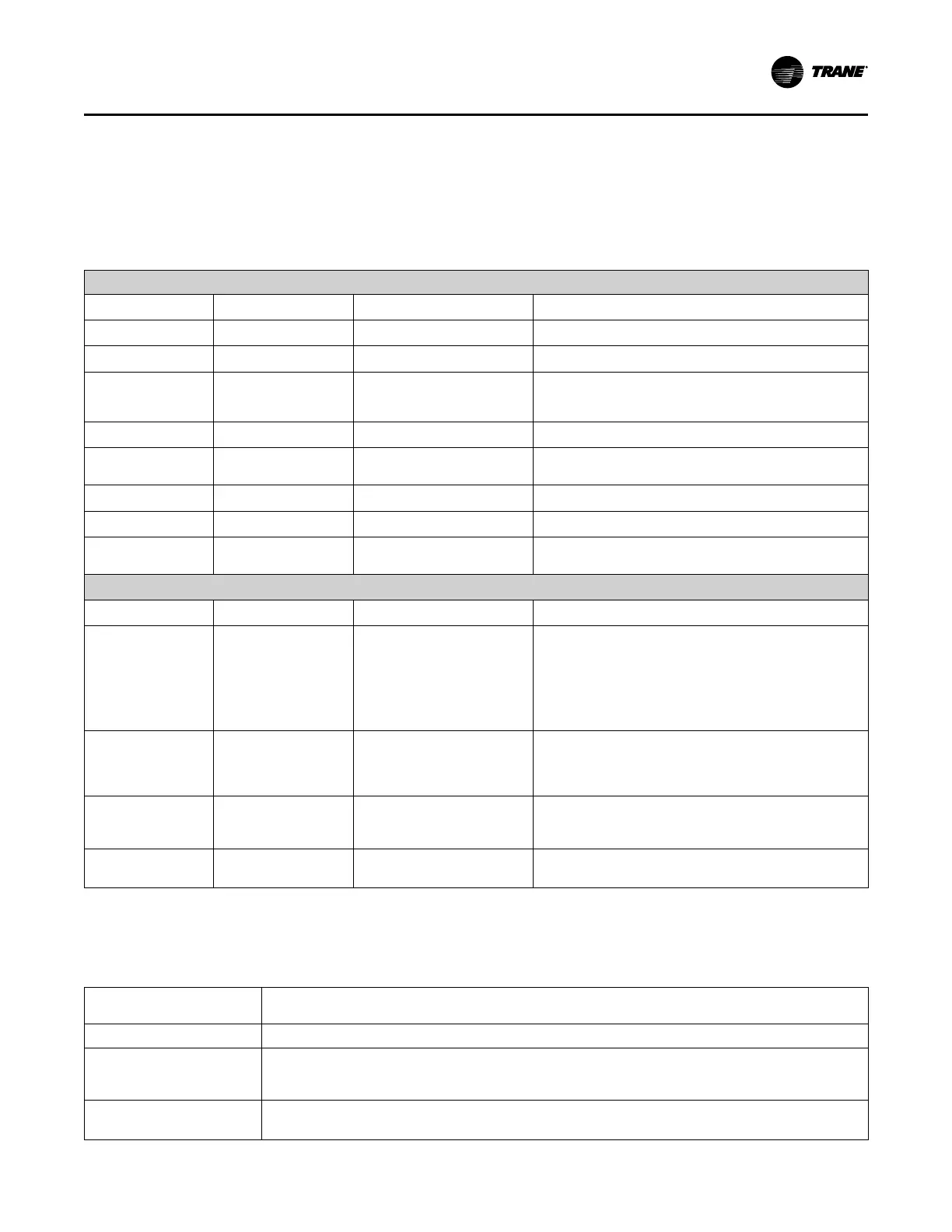
Table 79. Evaporative condenser models—maintenance and troubleshooting
Maintenance Schedule
Component
Action
Frequency
Comments
Fan Motor
None Required Non-grease bearings
Sump Pump Inspect / Clean 1 – 2 times per year Clean inlet openings to pump
Sump Inspect / Clean
1 – 2 times per year
depending on water hardness
and unit run time
Sump can be drained and hosed out using hose bib
provided at water fill solenoid valve. Vacuuming scale out is
an alternate method
Sump Float Switch Inspect 1 – 2 times per year
Float should be free for full float travel
Sump Float Make Up
Valve
Inspect for proper
water level
1 – 2 times per year
Spray Nozzles Inspect / Clean 1 – 2 times per year Inspection through access panel
Conductivity Sensor Inspect / Clean 1 – 2 times per year Clean sensor to ensure accurate readings
Conductivity
Controller
Inspect / Recalibrate 1 – 2 times per year
Recalibrate controller
Troubleshooting
Component
Problem Check Fix
Fan Motor Does not run
Condenser Fan Relay closure
and control voltage indicating
a call from compressor control
panel for the condenser fan to
operate. Sump Pump
Overload Trip. Fan Motor
Overload Trip. Fan fuse trip.
Check each motor overload and reset if necessary. Check
amp draw for each leg.
Sump Pump
Does not run
Sump Pump Overload Trip
Low Water Level or faulty float
switch. Unit in ‘Dry Mode’
Operation
Reset – check amps on each leg to determine if faulty
motor. Check and clean debris around float switch. Check
Ambient thermostat setting and mode of operation (close
on rise). See section 2 for T’stat setup instructions.
Sump Pump
Low Flow
Pump may be operating
backwards or impeller inlet
may be slightly blocked.
Change pumping direction by changing any two legs to the
pump motor. Disconnect Power and remove pump to
inspect for possible impeller obstruction.
Spray Nozzle Dry area on coil
Check for proper spray
pattern over each quadrant.
Remove debris from clogged nozzle.
Final Process
Record the unit data in the blanks provided.
Table 80. Unit data log
Complete Unit Model
Number:
Unit Serial Number:
Unit “DL” Number
(“design special” units
only):
Wiring Diagram Numbers
(from unit control panel):
SSeerrvviiccee aanndd MMaaiinntteennaannccee

 Loading...


