RT-SVX24Q-EN
73
• “OFF” - Indicates that the disconnect switch is
open, interrupting the main power supply to the
unit controls.
• “RESET/LOCK” - Turning the handle to this position
resets or disconnects the device. To disconnect, the
handle must be turned to the Reset/Lock position.
Pulling the spring-loaded thumb key out, so the lock
shackle can be placed between the handle and the
thumb key, locks the handle so the unit cannot be
energized.
WWAARRNNIINNGG
HHaazzaarrddoouuss VVoollttaaggee ww//CCaappaacciittoorrss!!
FFaaiilluurree ttoo ddiissccoonnnneecctt ppoowweerr aanndd ddiisscchhaarrggee
ccaappaacciittoorrss bbeeffoorree sseerrvviicciinngg ccoouulldd rreessuulltt iinn ddeeaatthh oorr
sseerriioouuss iinnjjuurryy..
DDiissccoonnnneecctt aallll eelleeccttrriicc ppoowweerr,, iinncclluuddiinngg rreemmoottee
ddiissccoonnnneeccttss aanndd ddiisscchhaarrggee aallll mmoottoorr ssttaarrtt//rruunn
ccaappaacciittoorrss bbeeffoorree sseerrvviicciinngg.. FFoollllooww pprrooppeerr
lloocckkoouutt//ttaaggoouutt pprroocceedduurreess ttoo eennssuurree tthhee ppoowweerr
ccaannnnoott bbee iinnaaddvveerrtteennttllyy eenneerrggiizzeedd.. FFoorr vvaarriiaabbllee
ffrreeqquueennccyy ddrriivveess oorr ootthheerr eenneerrggyy ssttoorriinngg
ccoommppoonneennttss pprroovviiddeedd bbyy TTrraannee oorr ootthheerrss,, rreeffeerr ttoo
tthhee aapppprroopprriiaattee mmaannuuffaaccttuurreerr’’ss lliitteerraattuurree ffoorr
aalllloowwaabbllee wwaaiittiinngg ppeerriiooddss ffoorr ddiisscchhaarrggee ooff
ccaappaacciittoorrss.. VVeerriiffyy wwiitthh aa CCAATT IIIIII oorr IIVV vvoollttmmeetteerr
rraatteedd ppeerr NNFFPPAA 7700EE tthhaatt aallll ccaappaacciittoorrss hhaavvee
ddiisscchhaarrggeedd..
FFoorr aaddddiittiioonnaall iinnffoorrmmaattiioonn rreeggaarrddiinngg tthhee ssaaffee
ddiisscchhaarrggee ooff ccaappaacciittoorrss,, sseeee PPRROODD--SSVVBB0066**--EENN..
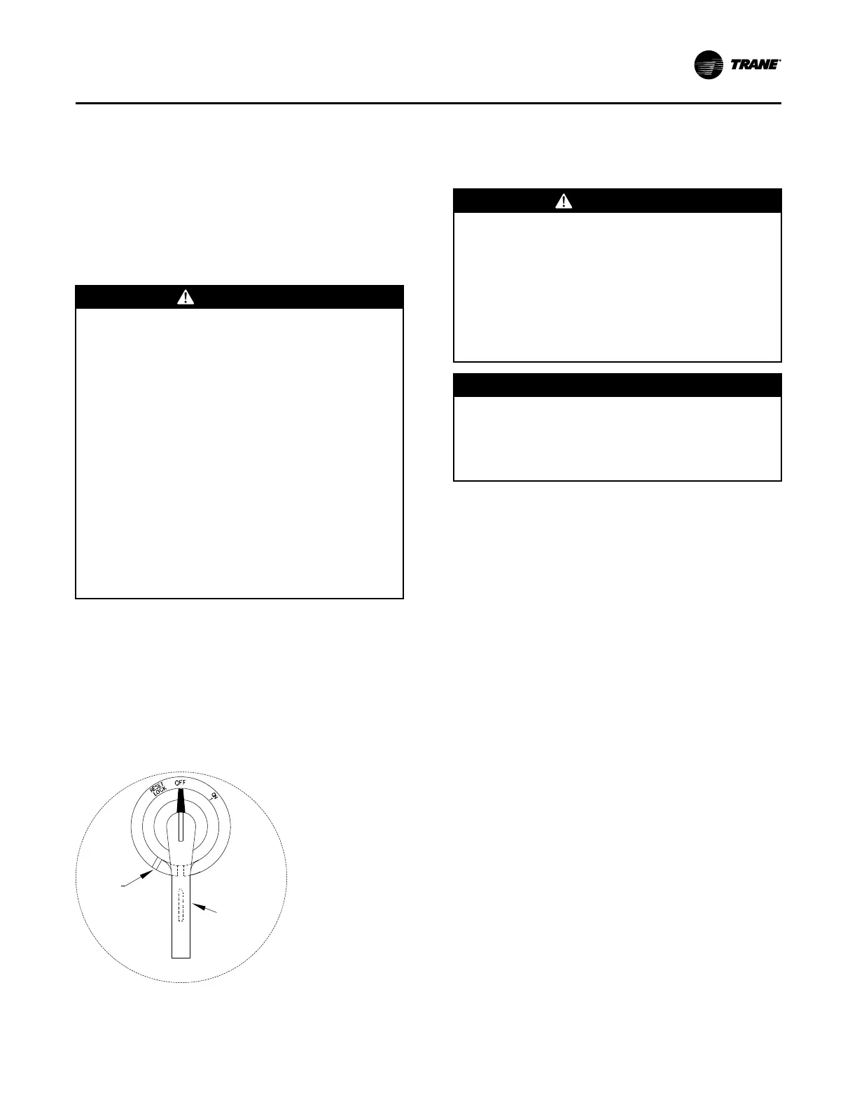
The handle can be locked in the “OFF” position by
completing the following steps (see Figure 56, p. 73):
1. While holding the handle in the “OFF” position,
push the spring loaded thumb key, attached to the
handle, into the base slot.
2. Place the lock shackle between the handle and the
thumb key. This will prevent it from springing out of
position.
Figure 56. Disconnect switch external handle
Locking
Slot
Locking
Thumb
Key Under
Handle
NNoottee:: All field installed wiring must conform to NEC
guidelines as well as State and Local codes.
An overall layout of the field required power wiring is
illustrated in Figure 57, p. 74. To ensure that the unit
supply power wiring is properly sized and installed,
follow these guidelines:
WWAARRNNIINNGG
LLiivvee EElleeccttrriiccaall CCoommppoonneennttss!!
FFaaiilluurree ttoo ffoollllooww aallll eelleeccttrriiccaall ssaaffeettyy pprreeccaauuttiioonnss
wwhheenn eexxppoosseedd ttoo lliivvee eelleeccttrriiccaall ccoommppoonneennttss ccoouulldd
rreessuulltt iinn ddeeaatthh oorr sseerriioouuss iinnjjuurryy..
WWhheenn iitt iiss nneecceessssaarryy ttoo wwoorrkk wwiitthh lliivvee eelleeccttrriiccaall
ccoommppoonneennttss,, hhaavvee aa qquuaalliiffiieedd lliicceennsseedd eelleeccttrriicciiaann
oorr ootthheerr iinnddiivviidduuaall wwhhoo hhaass bbeeeenn pprrooppeerrllyy ttrraaiinneedd
iinn hhaannddlliinngg lliivvee eelleeccttrriiccaall ccoommppoonneennttss ppeerrffoorrmm
tthheessee ttaasskkss..
NNOOTTIICCEE
UUssee CCooppppeerr CCoonndduuccttoorrss OOnnllyy!!
FFaaiilluurree ttoo uussee ccooppppeerr ccoonndduuccttoorrss ccoouulldd rreessuulltt iinn
eeqquuiippmmeenntt ddaammaaggee aass tthhee eeqquuiippmmeenntt wwaass nnoott
ddeessiiggnneedd oorr qquuaalliiffiieedd ttoo aacccceepptt ootthheerr ttyyppeess ooff
ccoonndduuccttoorrss..
• Verify that the power supply available is compatible
with the unit nameplate rating for all components.
The available power supply must be within 10% of
the rated voltage stamped on the nameplate.
• Use only copper conductors to connect the 3-phase
power supply to the unit.
Electric Heat Units
Electric Heat Units require one power entry as
illustrated in .
Use the information provided in Service Sizing data
and the “Power Wire Sizing & Protection Device
Equations,” to determine the appropriate wire size and
Maximum Over current Protection for the heaters/unit.
NNoottee:: Each power supply must be protected from short
circuit and ground fault conditions. To comply
with NEC, protection devices must be sized
according to the “Maximum Over current
Protection” (MOP) or “Recommended Dual
Element” (RDE) fuse size data on the unit
nameplate.
Provide grounding for the supply power circuit in the
electric heat control box.
Main Unit Power Wiring
Figure 58, p. 75 and Table 30, p. 75 lists the field
connection wire ranges for both the main power
terminal block and the optional main power disconnect
switch. The electrical tables beginning withTable 31, p.
76 list the component electrical data.
The electrical service must be protected from over
current and short circuit conditions in accordance with
NEC requirements. Protection devices must be sized
IInnssttaallllaattiioonn

 Loading...


