196
RT-SVX24Q-EN
5. Remove the tension gauge from the belt. Notice
that the small O-ring now indicates a value other
than zero on the force scale. This value represents
the force (in pounds) required to deflect the belt(s)
the proper distance when properly adjusted.
6. Compare the force scale reading in step 5 with the
appropriate “force” value in . If the force reading is
outside of the listed range for the type of belts used,
either readjust the belt tension or contact a
qualified service representative.
NNoottee:: The actual belt deflection force must not
exceed the maximum value shown in Table
74, p. 196.
7. Recheck the new belt's tension at least twice during
the first 2 to 3 days of operation. Readjust the belt
tension as necessary to correct for any stretching
that may have occurred. Until the new belts are
“run in”, the belt tension will decrease rapidly as
they stretch.
Table 74. Belt tension measurement and deflection ranges
Belt
Cross
Section
Smallest
Sheave
Diameter
Range
(In.)
RPM
Range
Belt Deflection Force (Lbs.)
Super Gripbelts and
Unnotched
Gripbands
Gripnotch Belts and
Notched Gripbands
Min.
Max.
Min. Max.
A, AX
3.0-3.6 1000-2500 3.7 5.5 4.1 6.1
3.8-4.8 1000-2500 4.5 6.8 5 7.4
5.0-7.0 1000-2500 5.4 8 5.7 8.4
B, BX
3.4 – 4.2 860-2500 – – 4.9 7.2
4.4 – 5.6 860-2500 5.3 7.9 7.1 10.5
5.8 – 8.6 860-2500 6.3 9.4 8.5 12.6
3V, 3VX
2.2 - 2.4 1000-2500 – – 3.3 4.9
2.65 - 3.65 1000-2500 3.6 5.1 4.2 6.2
4.12 - 6.90 1000-2500 4.9 7.3 5.3 7.9
5V, 5VX
4.4 – 6.7
500-1749
– –
10.2 15.2
1750-3000 8.8 13.2
7.1 –10.9 500-1740 12.7 18.9 14.8 22.1
11.8-16.0 500-1740 15.5 23.4 17.1 25.5
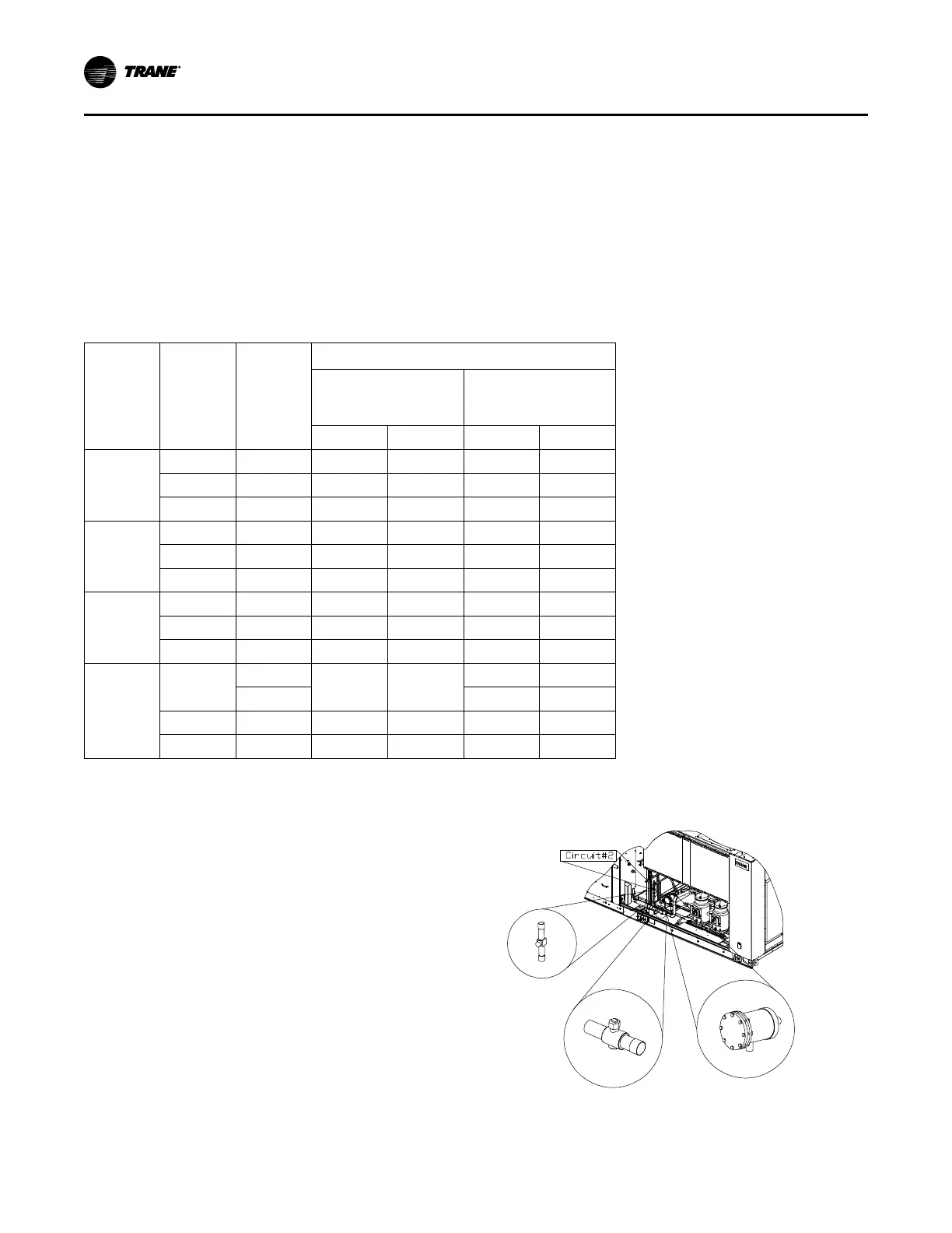
Scroll Compressor Replacement
The compressor manifold system was purposely
designed to provide proper oil return to each
compressor. The refrigerant manifold system must not
be modified in any way. See Figure 146, p. 196.
NNoottee:: Altering the compressor manifold piping may
cause oil return problems and compressor
failure.
Should a compressor replacement become necessary
and a suction line filter drier is to be installed, install it a
minimum of 16 or 25 inches upstream of the oil
separator tee.
IImmppoorrttaanntt:: Do Not release refrigerant to the
atmosphere! If adding or removing
refrigerant is required, the service
technician must comply with all Federal,
State and local laws. Refer to general
service bulletin MSCU-SB-1 (latest edition).
Figure 146. Suction line filter/drier installation
Sight glass
Suction service
va
lve
Replaceable core
drier
Note: These components are also located at circuit #1 side
SSeerrvviiccee aanndd MMaaiinntteennaannccee

 Loading...


