72
RT-SVX24Q-EN
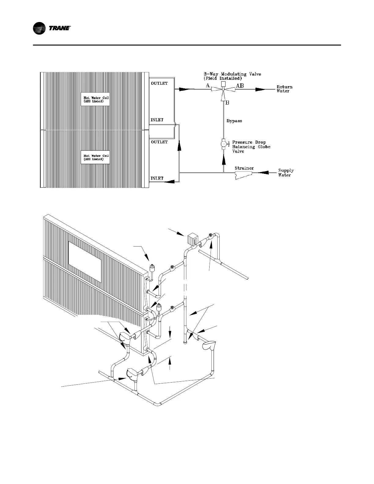
Figure 54. Hot water coil piping
Figure 55. Steam coil piping
2-Way
Modulating
Valve
Vacuum
Breaker
(2 locations)
Steam
Main
IN
(2 locations)
OUT
(2 locations)
Return
Main
T
y
p
e
NS
S
tea
m
Coils
(A
R
I
Lis
ted)
Use same size pipe
as Trap Connections
(3 locations)
Steam Trap
(Float & Thermostatic Type)
(3 locations)
Gate Valve
(3 locations)
Use same size pipe
as Steam Main
Use same size pipe
as Coil Connection
(2 locations)
Strainer
(3 locations)
12” Minimum
(both outlets)
Disconnect Switch with External Handle
Units come equipped with a factory mounted
disconnect switch with an externally mounted handle.
This allows the operator to disconnect power from the
unit without having to open the control panel door. The
handle has three positions:
• “ON” - Indicates that the disconnect switch is
closed, allowing the main power supply to be
applied at the unit.
IInnssttaallllaattiioonn

 Loading...


