RT-SVX24Q-EN
71
5. All return lines and fittings must be equal to the
diameter of the “outlet” connection on the steam
coil(s). If the steam trap connection is smaller that
the coil “outlet” diameter, reduce the pipe size
between the strainer and the steam trap
connections only.
6. Install a 1/2" 15 degree swing-check vacuum
breaker at the top of the return coil header using the
tapped pipe connection. Position the vacuum
breaker as close to the coil as possible.
NNoottee:: Vacuum breakers should have extended lines
from the vent ports to the atmosphere or
connect each vent line to the return pipe on
the discharge side of the steam traps.
7. Install a “Gate” type valve in the supply branch line
as close as possible to the steam main and
upstream of any other device.
8. Install a “Gate” type valve in the return branch line
as close as possible to the condensate return main
and downstream of any other device.
9. Install a strainer as close as possible to the inlet of
the control valve and steam trap(s). Steam trap
selection should be based on the maximum
possible condensate flow and the recommended
load factors.
10. Install a Float-and-Thermostatic (FT) type trap to
maintain proper flow. It provides gravity drains and
continuous discharge operation. FT type traps are
required if the system includes either of the
following:
a. an atmospheric pressure/gravity condensate
return
or
b. a potentially low pressure steam supply.
11. Position the outlet or discharge port of the steam
trap at least 12" below the outlet connection on the
coil(s). This will provide adequate hydrostatic head
pressure to overcome the trap losses and assure
complete condensate removal.
If two steam coils are stacked together, they must
be piped in a parallel arrangement. The steps listed
below should be used in addition to the previous
steps.Figure 55, p. 72 illustrates the recommended
piping configuration for the steam coils.
a. Install a strainer in each return line before the
steam trap.
b. Trap each steam coil separately as described in
Step 10Installation_Steam Heat Units and Step
11Installation_Steam Heat Units to prevent
condensate backup in one or both coils.
c. In order to prevent condensate backup in the
piping header supplying both coil sections, a
drain must be installed utilizing a strainer and a
steam trap as illustrated in Figure 55, p. 72.
Table 28. Hot water and steam coil connection sizes
Hot Water Coil Steam Coil
Unit
Size
Sup-
ply
Re-
turn
Drai-
n/
Vent
Sup-
ply
Re-
turn Vent
90-
162
Ton
2 ½ 2 ½ ½ 3.0 1 ¼ 1 ¼
Notes:
1. Type W coils, with center offset headers, are used in Hot
Water units; Type NS coils are used in Steam units.
2. Hot water and Steam units have multiple headers.
3. All sizes are in inches.
4. All connection threads are internal.
Table 29. Hot water and steam heat connection
dimensions
Tons A B Y Diameter
90-118
276 9/16 290 5/16
18 5
120-162
341 5/16 355 1/16
18 5
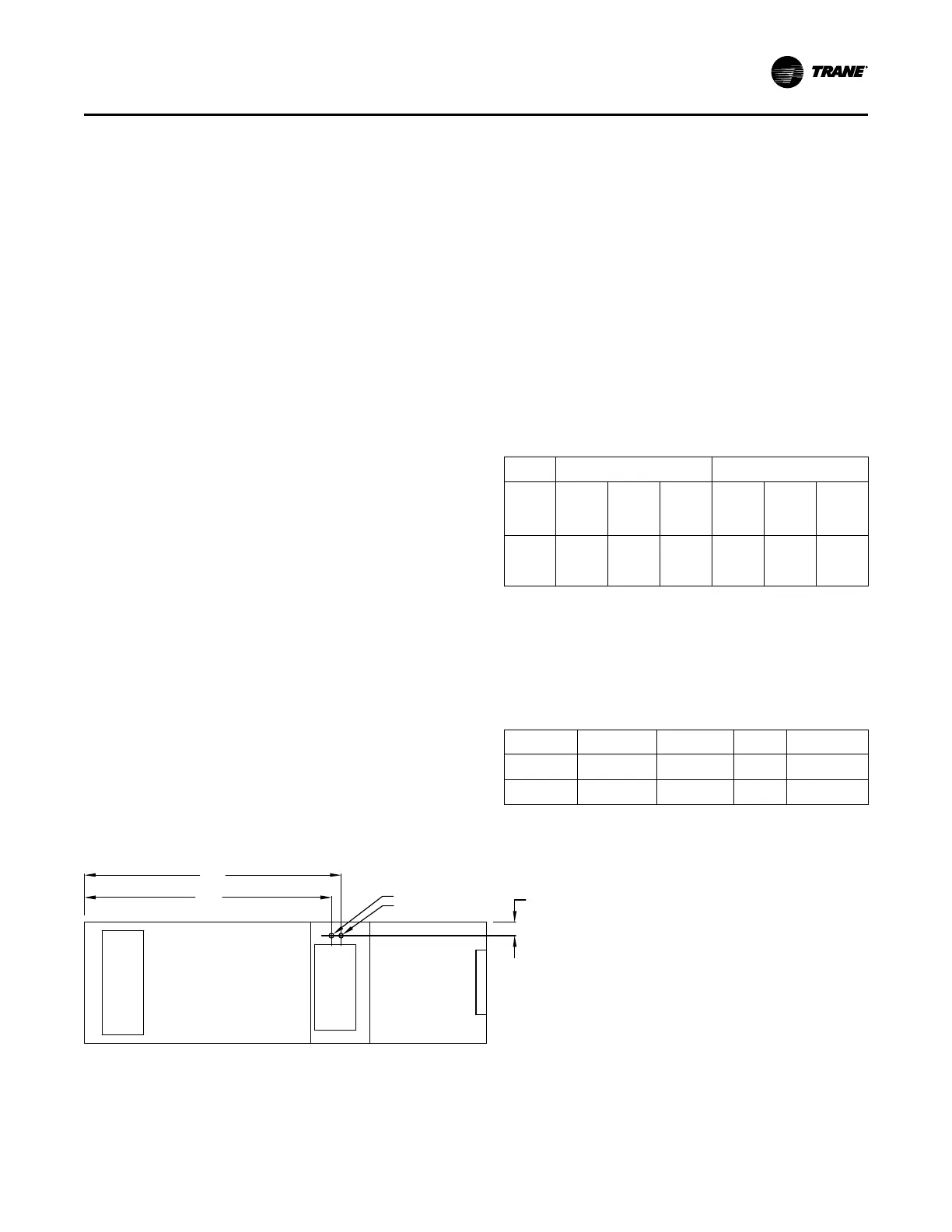
Figure 53. Hot water and steam heat connection location
A
B
Y
Supply Air Opening
Return Air Opening
Unit bottom view
Inlet
Controls
Outlet
Recommended
IInnssttaallllaattiioonn

 Loading...


