INSTRUCTION MANUAL
UG30 CONTROL
6 (44)
mP30-UG30 - Rev. 1.5 - Date: 18-03-2004 EN
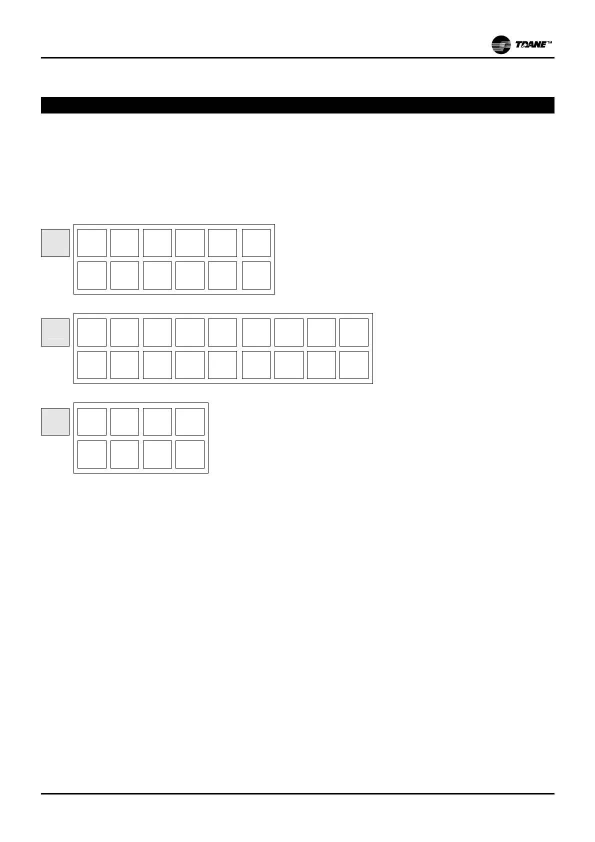
LAY-OUT OF UNIGUARD BASE UG30/mP30 CIRCUIT
The figure shows the rear of the UG30/mP30 control, with input and output terminals.
The following are shown in the figure:
- low down: connectors ("1" - "2" - "3"), with the analogue and digital inputs and outputs;
- lay-out for the clock circuit (optional);
- lay-out for the RS485 serial circuit (optional);
1
C5
C3/4
OUT3
C1/2
Y1
Y2
OUT5
OUT4
OUT2
OUT1
GND
GND
2
G0
B4
B2
B3
ID2
ID4 ID6 ID8 ID10
G
B1
GND
+V
ID1
ID3 ID5 ID7 ID9
3
C6
NO6
C7
NC6
NO7