INSTRUCTION MANUAL
UG30 CONTROL
mP30-UG30 - Rev. 1.5 - Date: 18-03-2004 EN
43 (44)
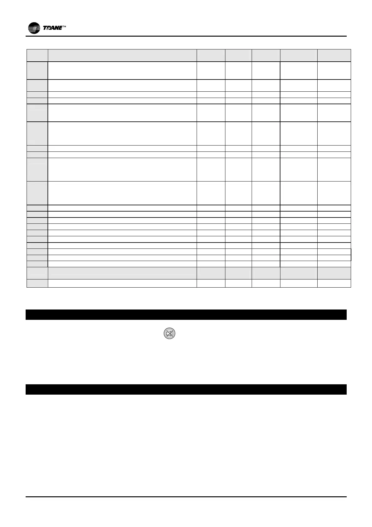
GLb GENERAL
Type Minimu
m
maximum Measurement
unit
Default
H1 Unit model FACTORY 0 2 flag 0 (DX-DX/S)
1,2 (CW-
CW/S)
H2 Number of connected units FACTORY 0 6 flag 0
1…6
H3 Address of connected unit FACTORY 1 6 flag 1…6
H4 Rotation time between all connected units FACTORY 0 250 ore 168
H5 Functioning mode of chilled water outputs OUT1-OUT2 FACTORY 1 5 flag 3 (CW)
1 (DX/S)
1 / 2 / 5 (DX)
H6 Functioning mode of hot water outputs OUT3-OUT4 FACTORY 0 4 flag 0 / 3 / 4
(CW-DX)
0 / 1 / 3
(CW/S-DX/S)
H7 3 point valve excursion time end dumper FC FACTORY 0 600 sec 150
H8 Humidifier present FACTORY 0 1 flag 0 / 1
H9 Dehumidification present FACTORY 0 8 flag 3 (CW)
8 (CW/S)
0 / 2 (DX)
5 (DX/S)
HA Digital output function DO7 FACTORY 0 3 flag 0 (CW) / 3
2 (CW/S) / 3
1 (DX) / 3
2 (DX/S) / 3
Hb Output function Y2 FACTORY 0 2 flag 0
HC Functioning of B2 sensor FACTORY 0 3 flag 0
Hd Functioning of B3 sensor FACTORY 0 1 flag 0
HE Digital input ON/OFF USER 0 2 flag 0 / 1 / 2
HG Delay at power up USER 0 300 sec 0
HH USER Password USER 0 200 -
22 (**)
Hi Keyboard lock-out USER 0 1 flag 0
HL Parameters setting FACTORY 0 3 flag 1
Ho Serial address for supervision network USER 1 200 - 1
HP Serial baud rate for supervisor USER 1 5 flag 5
Cloc CLOCK
Type Minimu
m
maximum Measurement
unit
Default
rt Hour-bands setting USER 0 2 flag 0
(**): "USER" password contained in envelope enclosed with manual
MEMORY RESET
With the control programme on, press the button
in order to reset the parameter values.
After having performed this first step:
- Set the default values, see above paragraph “Default Values”;
- Configure the devices and the sensors fitted according to the type of unit, adjust the set-points that needed to
be different from the default values.
APPENDIX – mask flowcharts