INSTRUCTION MANUAL
UG30 CONTROL
mP30-UG30 - Rev. 1.5 - Date: 18-03-2004 EN
7 (44)
INPUTS AND OUTPUTS
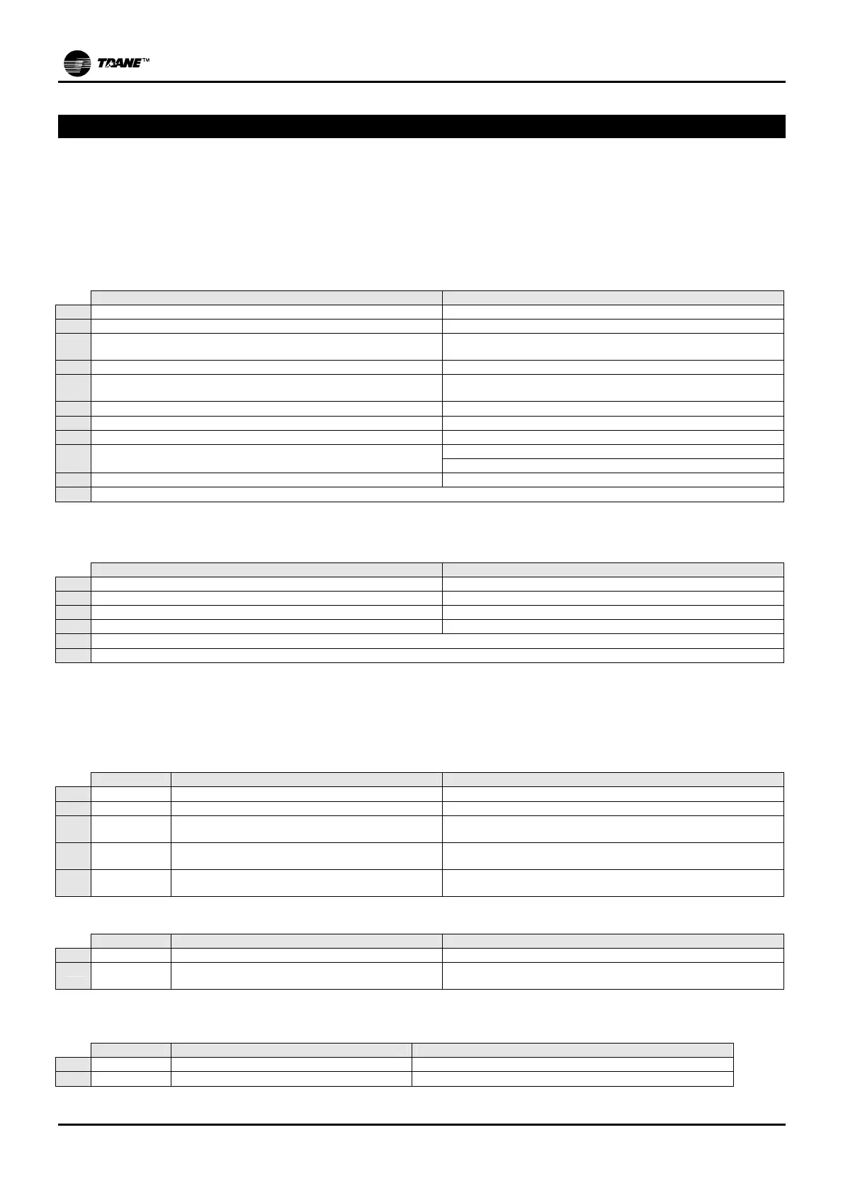
The following tables shows information on inputs and outputs according to the type of selected unit.
CW = 'MERCURY' chilled water air conditioner;
CW/S = 'JUPITER' chilled water air conditioner;
DX = 'MERCURY' direct expansion air conditioner with 1 or 2 compressors.
DX/S = 'JUPITER' direct expansion air conditioner.
DIGITAL INPUTS – Connector 2
Equipped with 10 24Vac digital inputs.
CW - CW/S DX - DX/S
ID1
Remote ON/OFF Remote ON/OFF
ID2
Air flowswitch Air flowswitch
ID3
Dirty filters flowswitch
(standard issue on CW/S unit, optional extra on CW unit)
Dirty filters flowswitch
ID4
Safety thermostat for heating elements Safety thermostat for electrical resistors
ID5
Alarm from temperature and humidity external sensors, and from
flooding sensor (optional)
Alarm from temperature and humidity external sensors, and from
flooding sensor (optional)
ID6
Humidifier alarm from circuit CDA303 Humidifier alarm from circuit CDA303
ID7
-- Circuit 1 high pressure
ID8
-- Circuit 1 low pressure
ID9
-- Circuit 2 high pressure
Compressor thermal breaker
ID10
-- Circuit 2 low pressure
GO
Common for inputs 1 –10
ANALOGUE INPUTS – Connector 2
Equipped with 3 analogue inputs for NTC sensors and 1 active probe 0-1Vdc / 4-20mA.
CW - CW/S DX - DX/S
B1
Room temperature Room temperature
B2
External air temperature for summer/winter changeover External air temperature for summer/winter changeover
B3
Room relative humidity Room relative humidity
B4
STM delivery temperature STM delivery temperature
GND
Common for analogue inputs
+V
Power supply for active sensors 14Vdc (max.30mA)
DIGITAL OUTPUTS
The card is equipped with 7 outputs including: 1 200 Vac relay, with exchange contact; 1 200 Vac relay, with
normally opened contact.
Digital outputs – Connector 1
CW - CW/S DX - DX/S
DO1 C1/2 – OUT1
Cold water valve + (opens) Compressor circuit 1
DO2 C1/2 – OUT2
Cold water valve - (closes) Compressor circuit 2
DO3 C3/4 – OUT3
1
st
stage for heating elements/
Hot water valve + (opens)
1
st
stage for heating elements/
Hot water valve + (opens)
DO4 C3/4 – OUT4
2
nd
stage for heating elements/
Hot water valve - (closes)
2
nd
stage for heating elements/
Hot water valve - (closes)
DO5 C5 – OUT5
Fan
Triggering by fire-smoke sensor
Fan
Triggering by fire-smoke sensor
Digital outputs with relays – Connector 3
CW - CW/S DX - DX/S
DO6 C6-NO6-NC6
Serious alarm Serious alarm
DO7 C7-NO7
Dehumidifying solenoid-valve (CW)
Available for non-serious alarm warning (on CW/S)
Dehumidifying solenoid-valve (DX)
Available for non-serious alarm warning (on DX/S)
ANALOGUE OUTPUTS – Connector 1
Equipped with a 0-10Vdc analogue output and 1 phase cut-out output.
CW - CW/S DX - DX/S
Y1 Y1 – GND
Humidifier control Humidifier control
Y2